
In my post on how much audio bandwidth was really required, I posited that there was not sufficient benefit to justify the impacts of pushing the low end frequency response of our tube amps down to 20Hz. As part of that post I included the following statement.
“In order to pass really low frequencies the primary inductance of the output transformer must be rather large. Now the difference in frequency between 20Hz and 40Hz is a full octave. This means that a transformer designed to pass 20Hz at the same level as one designed to pass 40Hz must have a primary inductance which is twice as large. This equates to a much larger and more expensive coil and also introduces complexities at the upper end due to interwinding capacitances. This drives one to rather expensive solutions.”
Now there are those that may suggest that, given the overall cost in time and materials to produce a high fidelity amplifier, the additional size and expense in the output transformer is entirely justified. The rhetorical questions which immediately come to mind include “Why not simply spend the additional funds and get the bigger transformer?” and “Isn’t larger primary inductance in an output transformer better?”. Unfortunately, like most things in Engineering, there are tradeoffs involved. So my goal here is to examine those tradeoffs and explore the possibility that those large transformers might be doing more harm than good in your output stage operation.
First I would like to explore why the larger primary impedance of the output transformer supports a lower frequency roll off. Without going through the derivation, the low frequency roll off of a transformer coupled stage (which is what a transformer coupled output stage is) is defined by the following relation:
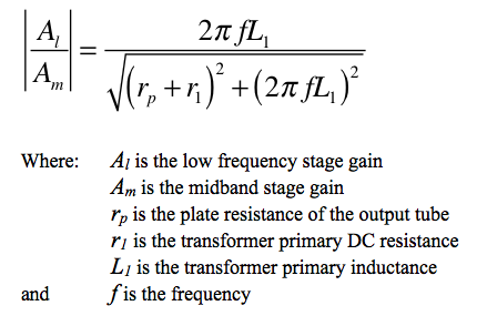
This formula relates the low end frequency response to the midband gain of the output stage. It is a mathematical definition of low end roll off. From this relation it is simple to see that for any given frequency, the larger L1 becomes, the closer to 1 the relation becomes and hence the lower the low frequency rolloff. This is at the heart of why larger transformers produce better low end performance. If one was to only look at this relation, it would drive you to want larger and larger output transformer primaries, in order to drive the low end performance of the amplifier. However, there is something else to consider.
It is important to understand the conditions under which a normal output stage operates. Take for example a simple single ended triode, cathode biased output stage with a transformer load. At zero input voltage, the output tube will be operating at the DC bias point determined by the B+ voltage, the bias resistor, the transformer dc primary resistance, and the plate characteristics of the output tube. Now, if the tube were distortionless (indicating that all harmonic distortion terms were zero) then regardless of the drive level, the bias point would remain at the dc bias point. The issue arrises because the tubes are not distortionless.
Because of the distortion in a tube, there is a shift in bias current driven by the magnitude of the even term harmonic distortions. This change means that when the output tube is being driven hard, the dynamic bias point (and current) can be significantly different than the dc bias point (and current). What this means is that there must be a transition between bias currents when there is a transition between drive levels. So what does all this mean?
Lets look at the example of a rapid transition in volume. In classical music this could be a trumpet blast or the crash of cymbals. In both cases, the level of the music, and hence tube drive and load current, changes suddenly. This sudden change is the crux of the problem. When the current in an inductor suddenly changes, there is an induced voltage in the inductor proportional to the inductance and the rate of current change. The magnitude of this voltage is to oppose the change in current. Normally this is written as:
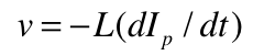
This voltage acts to oppose the B+ voltage and hence limit the plate current in the output stage. Once this happens, the current begins to increase exponentially until the steady state dynamic operating point is reached. In effect, this phenomenon limits the transient dynamic response of the output stage. And because of the relation above, it can be seen that the larger the primary inductance of the output transformer, the slower the transient response will be.
So this is the technical explanation, but what does it mean sonically. Lets return to my example of the trumpet blast. A trumpet blast in classical music is an example of a marcato fortissimo or very strong, marked transition in the music. Such a transition will markedly shift the operating point current from one value to one much higher. This transition cannot occur instantaneously but will take time to occur dependent on the size of the primary inductance. The effect of this phenomenon is one of blunting, or slowing the transition. Additionally, the nonlinear nature of the exponential ramp will increase distortions as the transitions take place. The net effect being that a transition which is intended to be sharp and crisp, becomes muddled and distorted. In some cases, the effect is minor. But in large transitions, the effect can rob the music of important dynamic character.
Sometimes you’ll hear an amplifier described as “light” or “responsive”. This is an amplifier that has good transient response. One that can rapidly change levels without undue lags or distortions. On the other end of the spectrum an amp may be described as “slow”, “dull”, or “muddy”. These are examples of an amplifier which has poor transient response. It is one that sounds fine with music that is melodious, which ebbs and flows easily, but cannot handle the rapid changes that a dynamic score requires. And note that this is not just an issue at low frequencies, the relation above is independent of frequency. Rapid changes in the mid and upper bands are just as affected as the low frequency notes.
Could this be the explanation for why those some of those lower cost transformers seem to get such praise from the DIY community? The Edcor GXSE and XSE transformers seem to get very favorable reviews from some builders in spite of their 40Hz and 70Hz respective low end roll off frequencies. So lets compare several transformers of approximately the same primary impedance. I will start first with some “full bandwidth” 20Hz to 20kHz models. From “One Electron” lets look at the UBT-2 4800Ω unit, from Hammond I’ll choose the 1628SEA and 1642SE 5000Ω units, and from Edcor I’ll look at the CXSE25-8-5K.
Of these transformers, the UBT-2 gets the highest reviews on the web. Reviews of the Hammond and Edcor models are next in line and tend to run neck in neck. So what do we know about these output transformers? Well, here are their primary impedances and inductances:
One Electron UBT-2    4800Ω   29H
Hammond 1628SEA       5000Ω   48H
Hammond 1642SE        5000Ω   53H
Edcor CXSE25-8-5K     5000Ω   50H
This illustrates a possible insight. The highest subjectively rated of these transformers is actually the one with the lowest primary inductance. This is a trend which seems to go against the conventional wisdom. Most believe that larger primary impedance means a better output transformer. However, technically we know that the UBT-2 is going to have almost half the transient response time of the Hammond and Edcor transformers if used in the same amp at the same bias point. This could well be the reason that it tends to beat out the others in subjective listening tests. Now just for illustration, lets throw a 40Hz roll off transformer into the mix; the Edcor GXSE10-8-5K. Here is the same list given above (for perspective) with the new transformer added.
One Electron UBT-2    4800Ω   29H
Hammond 1628SEA       5000Ω   48H
Hammond 1642SE        5000Ω   53H
Edcor CXSE25-8-5K     5000Ω   50H
Edcor GXSE10-6-5K     5000Ω    5H
This is even more illustrative. By giving up those 20Hz on the low end, this transformer has only 1/10 the primary inductance of its brother the CXSE25-8-5K. Now some of this is obviously due to its lower power rating, but it is still a significant reduction. In theory, this little output transformer will have ten times the transient response of the larger units.
So this is my thesis. The reason that the smaller output transformers have such a loyal following among the DIY community is not simply a matter of price. It is a matter of overall performance. If you build an amplifier and forgo the lowest of the low frequencies by using one of these, you will get much better transient performance from your amplifier. And this transient performance adds much more to the music than the frequencies between 20Hz and 40Hz ever could.
Questions or comments? Drop me a note and let me know what you think.
Are you sure the primary inductance have any effect on transients response ?
Are you sure that it’s not the leakage inductance which is accountable for slow transients ?
And that because leakage inductance is linked to the number of turns of the primary (so, the inductance of the primary), we thought that it’s the primary inductance which cause slow transients ?
Yes, I’m sure. This is simple mater of magnitudes. The leakage inductance is a small fraction of the primary winding inductance. At audio frequencies, the leakage inductance (in a well made transformer) is swamped by the impacts of the winding inductances and the core characteristics.
For a good analysis without an overload of mathematics see Reich, “Theory and Applications of Electron Tubes”, McGraw-Hill, 2nd Ed., Sec 6-13, pp176-182 (1944). (Full text available at this link.)
For a more rigorous analysis see Koehler, “THE DESIGN OF TRANSFORMERS FOR AUDIO-FRE-QUENCY AMPLIFIERS WITH PREASSIGNED CHARACTERISTICS”, Proc. IRE, Vol 16, pp1742-1770 (1928). (Available from most Engineering technical libraries.)
I sent an email to SACThailand, manufacturers of “Silk” output transformers, asking them what there inductance was at 1KHz. They list their inductance at 20Hz (20H for a 12W 6600Ohm primary for their S-505 model), but not 1KHz, the frequency that Hammond uses to list inductance. I mentioned what I had learned from this blog, e.g., low inductance transformers “get much better transient performance” albeit at the cost of low end extension. I also mentioned that I planned on using an active crossover so the valve amp I am planning wouldn’t receive signal below 200Hz. Their reply was interesting. They said that inductance at 1 KHz was generally 30 to 40% lower than at 20Hz. Which means between 12-14H at 1KHz, which is fairly low somewhere between One Electron’s UBT-2 and Edcor’s GXSE10-6-5K. They list the -3 dB frequency response as 30Hz – 70KHz. So it seems they are not so swayed by the quest for 20Hz.
They also mentioned “I understand your desire to excel your project but lowering the inductance will also effect distortion performance. The transformer will saturate easily even at mid frequency”. So perhaps there is a trade off between increased transient performance, from lowering inductance, and the distortion generated from core saturation?
I am deciding on what output transformers to get for my single ended triode strapped 6P15P project. I live in Australia and considering shipping I can get a pair Hammond 125ESE 15W transformers for about half the price of the Silks or similar Edcors. Hammond lists the inductances as between 5 and 32H depending on the speaker load and which output tap is used. For the configuration I have planned, 8 Ohm load on the green (8Ohm) tap with a 10,000Ohm primary, I would have an inductance of 8.2H, not far from the small Edcor’s. I am not sure if core saturation would be an issue?
I have never built an amplifier before, so am keen to get Matt’s or anyone else’s thoughts here.
Kind Regards, Ben
Ok, there’s a lot to unpack here. First I want to make a few points.
1) Inductance, the number we measure in Henrys, is not strictly speaking frequency dependent. Now measured across three decades of frequency any real inductor is going to vary. However, any variance more than about 20% is excessive and probably due to marginal magnetic circuit design. Reactance is, of course, frequency dependent (being Xl=2πfL) but that really shouldn’t enter into the discussion.
2) The only way to properly measure primary inductance is with all other windings open circuit. Anyone quoting different inductances based on loading is trying to conflate some other measure of operation or performance (for example, referenced primary impedance) with primary inductance.
3) The transformer is first and foremost, a TRANSFORMER. It’s only at the ends of its pass band where we begin to look at other parameters. At low frequency we examine the primary inductance because it is here were we lose energy at low frequencies. At high frequency we look at winding capacitance because that is where we lose energy at high frequencies. It is simply assumed that the parameters of the transformer are such that we get good midband performance, including transient response.
4) In most of its pass band, a transformer acts as neither a pure inductor or a capacitance. These characteristics do affect the performance, but neither dominates. It is a complex two port network that requires deep analysis to truly understand its operation.
In my opinion, the issue of core saturation is a red herring. If a transformer is rated at a certain max DC current and a power level, the the core will have been designed to handle that level of magnetic flux without saturation. This is maximum flux density. The inductance will depend mostly on the core permeability. These are not the same. The Hammond specification sheet for the 125ESE specs the primary inductance at 5.43H. This is smaller than what I generally measure with the Edcor GXSE transformers but similar to the Edcor XSE series.
The 125ESE has a maximum DC current rating of 80mA. This is a good match for the 6P15P’s maximum cathode current rating of 90mA. I am guessing that you probably don’t want to go above about 50mA for the triode strapped 6P15P in an SE topology. In reality your bias point is going to be more critical than your OT primary inductance.
Don’t read too much into this post. I was trying to make the point that there are tradeoffs when trying to get down to 20Hz with the output transformer that can hurt other characteristics of the amplifier. Look at the first equation again. The plate resistance driving the tube can be a big, or a bigger factor, than the primary inductance in getting down to 20Hz. When a manufacturer says that their transformer has a “bandwidth” they are making a whole set of unknown assumptions. Many of which will not hold in your design. As an example, go look at the measured pass band on the 6AS7 Purpleheart SET. Edcor rates the GXSE only down to 40Hz but the 1dB passband IN THIS AMPLIFIER goes down to ≈15Hz. That’s one and one half octaves below the manufacturer specification point. I measured the primary inductance of this transformer at ≈7.5H.
My rule of thumb is, if you want a fast and agile amplifier, avoid measured primary inductance above 20H to 30H. Just remember that there is a lot more to low frequency transformer performance than just primary inductance.
I just stumbled on the link here from diyaudioprojects.com/forum and I’m glad I did. I have a SE amp I built with the CXSE25-8-5K transformer and was just starting to consider trying to ‘upgrade’ the transformer. This article put a new direction on my search and I may even try the smaller edcor transformer because I don’t think most of the music I listen to has much below 40 hz. I know low piano notes can get down there but I don’t know how common those are in most music.
How does primary DC resistance play into the comparisons? Would the UBT-2 with 432 ohms have any noticeable difference from a Transcendar TT-021-OT with 215 ohms?
In general, the effect of the primary resistance of most transformers is dwarfed by the output impedance of the driver stage (the rp term in the equation above). This is especially true when the amplifier employs no NFB.
Since the total low end rolloff of the stage is driven by both the sum of the resistances and the primary inductance, it is necessary to reduce the resistances and increase the inductances to achieve very low rolloff frequencies. However, the difference between 432Ω and 215Ω would only be significant if the output impedance of the power stage were already very low.
Matt, Have you considered testing and comparing any TOROIDIAL output or interstage transformers. These might make a difference….Mike J.
This really is an issues with the primary inductance. The differences in E-I verses toroidal magnetics won’t make a difference in this case because the primary inductance is not affected by the change. Toroidal cores are all about reducing the leakage inductance in transformer. This can have an effect on the high frequency response but not the low end. And remember, part of good transformer design is to try and make sure that SQRT(Le/Ce)/Re is as close to unity as possible. So lower Le means lower Ce which means a smaller transformer. So, at its heart, toroidal cores are more about saving money than they are about superior performance.
I just built an experimental 6550 based UL – SE amp with the Edcor GXSE10-6-3.5K. Puts out about 10 watts. The first thing I noticed about this amp was how accurate and fast it sounds. Your theory makes sense to me! It’s driving some big speakers that are pretty efficient but have very complex crossovers. The amp drives them well pretty loud (you can tell when they run out of steam for sure) and sound great with complex modern and classic rock, jazz and electronic music. Very textural, detailed, fast and rich sounding.
Love your site and blog, very informative! I live in the PNW too..
I’m glad you like the site. I really like the little Edcor GXSE series of transformers. They always sound great in my builds.
This is a very, very good advice from Matt. I built the Single-Ended UL 6L6GC amp with the GXSE15-5K (8 OHM). The circuit is simple and straightforward, and the sound is really, really good. The amp is mated with three-way medium-size loudspeakers.
I would like to suggest other DIY tube amp builders to read this article from Matt and make a smart decision on the choice of practical output transformers based on Matt’s explanation.
Vu, Germany
Excellent article and observation. My single driver (so bi-amping is not an option) speakers -3db is somewhere just below 30hz. I have already lost a bit of low end so the lower inductance transformer would seem to make quite a hand shake with speakers like mine.
Yet another reason to bi-amplify. Transistor woofer amp, tube mid-hf amp doesn’t need the bottom 1 ~2 octaves. Smaller, less expensive OPT with better transient performance, no LF passive low-Z crossover between amp and woofer, and a host of other advantages.