
I’ve been working on a new SET amplifier design. It’s a modern (well at least more modern) approach to an all triode signal chain with a relatively high power output (about 7.5w into the output transformer). But there’s a catch, I’ve never personally used this power tube before and there really isn’t much information about it floating around the internet. You see, instead of going with some huge transmitter output tube like the 211 or an over hyped DHT like the 2A3 or the 300B, I took a different approach. I decided on a very linear, high power, pass triode; the 6336A.
This tube has several advantages over the DHTs and transmitter tubes commonly used for the big SETs. First, it has two power triodes in a single envelope. This allows me to control the overall size of the final amp without worrying about airflow around the power tubes or tube co-heating. Second, these triodes have unipotential cathodes. This means no specialized filament power supplies and no worry about heater supply biasing and grounding. Third, these triodes are very well built. With a special extra hard and thick glass envelope, massive carbon slab plates each with a 30W continuous duty power dissipation capacity, built to rigid electrical and mechanical specifications (including substantial shock and vibration), and using a modern 8-pin octal base these tubes will take whatever abuse you can throw at them. Fourth, and finally, the 6336 at moderate loads are at least 10dB more linear (i.e 10dB lower second harmonic) than the best of the DHTs and at least 20dB more linear than most of the transmitter power triodes. In most listening tests, the tubes should really shine.
So I decided that before I invested a lot of time and energy in building the first amplifier, I would do some preliminary work with the tube to get comfortable with it’s characteristics. I got my hands on several tubes of different brands and put together a power stage prototype. Here it is.
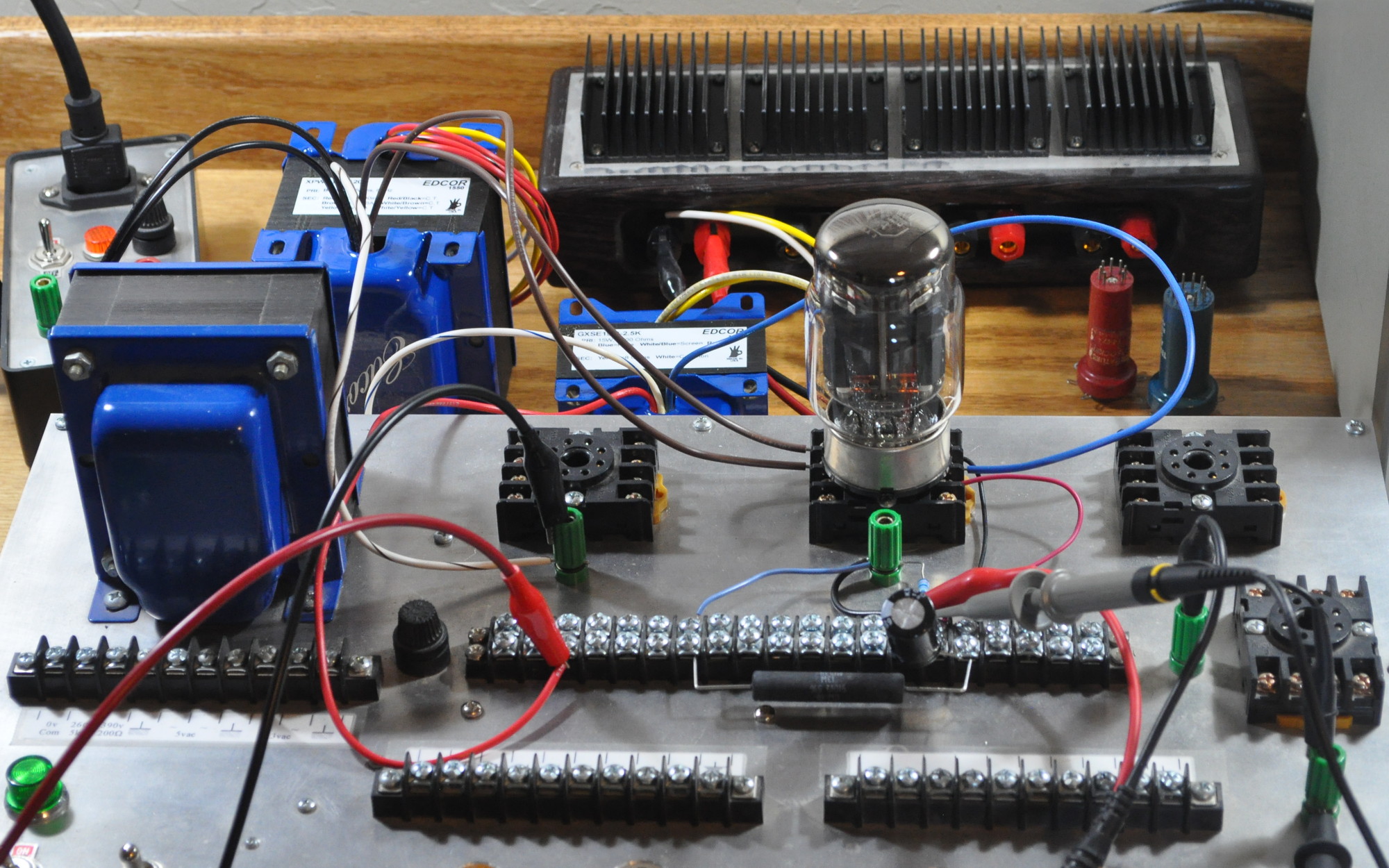 The tube here is running cathode biased through an output transformer. The large transformer in the back is the power transformer for the first amplifier. In this prototype it is only supplying the heater voltage for the 6336 because it’s the only thing I have capable of supply the 6.3V 5A heater power for this tube. When I said “big SET” I meant it. That’s 31.5W of power just for the heaters on this big tube. The B+ is being supplied by my bench power supply.
I’ve learned some interesting things about this particular tube. First, the linearity is exceptional. The power stage is very clean. Second is that this tube runs hot. I did not fully appreciate how much heat is generated by the 31.5W heaters and ≈24W of dissipation for each plate. Even running only one plate this tube gets pretty warm after a while. I will have to be sure to take this into account in my design.
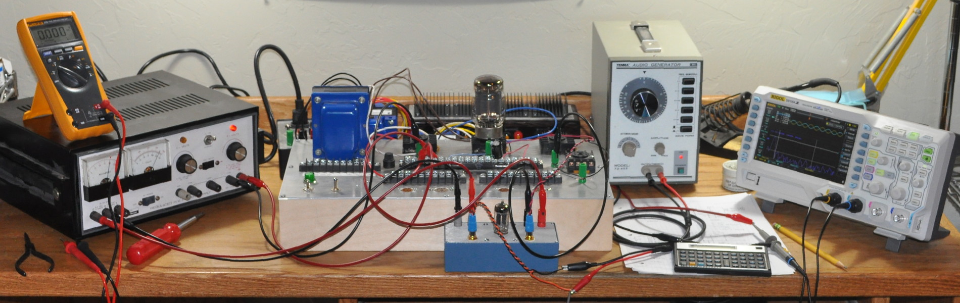
While driving the tube with my signal generator alone, I can only generate about 50mW into the 8Ω load. At this level the distortion is not measurable with my equipment. Basically this means that the 2nd harmonic distortion is well below 0.5% (-46dBv). So to get an idea of the total distortion I needed more drive. Luckily I had recently completed a brassboard of the driver circuit for this very amp. So I grabbed it off the shelf and put together a full one channel configuration prototype. Here it is.
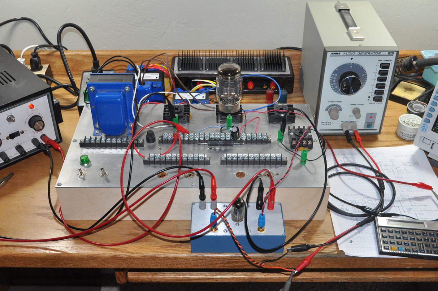
This configuration, while clearly still a prototype, allowed me to “ring out” the new power tube. This configuration allowed me to cleanly get to 6.35W into the 8Ω resistive load with 3.4% THD (virtually all 2nd harmonic). This gives a Ds value of 0.54%/W; this is a very good result and much cleaner than most 300B power stages. By “cleanly” I mean no visible flattening (clipping) on the output waveform and no visible harmonic structure higher than 2nd harmonic. If I pushed the stage to 8W I get some mild clipping in the output waveform, but the THD is still less than 5%. However, there is clearly a visible harmonic structure in the spectrum plot with the typical decreasing harmonic levels. This spectrum looks much more like a solid state amplifier pushed to it’s limits.
So what did I learn about this “new to me” power tube? Overall, I learned that it should make an excellent SET power tube. I also learned that it is very linear, handles large power dissipations well, produces less distortion than would be indicated by it’s characteristic curves, will produce over 6W very cleanly, and will produce 8W with an acceptable level of distortion. This tube, in a well built amplifier with good iron, should blow most 300B amps out of the water. Now I just need to design and build the amp.
Great design Matt. Any recommendations on choosing the 6336 tube. How closely matched do they need to be? The tubes available seem to vary quite a bit between the two triodes.
Yes, write a book on ‘Designing Tube amps’ 😀
There are really only two different types of 6336 tube widely available. They are the older basic 6336 with a large metal plate structure including integral cooling fins shown here.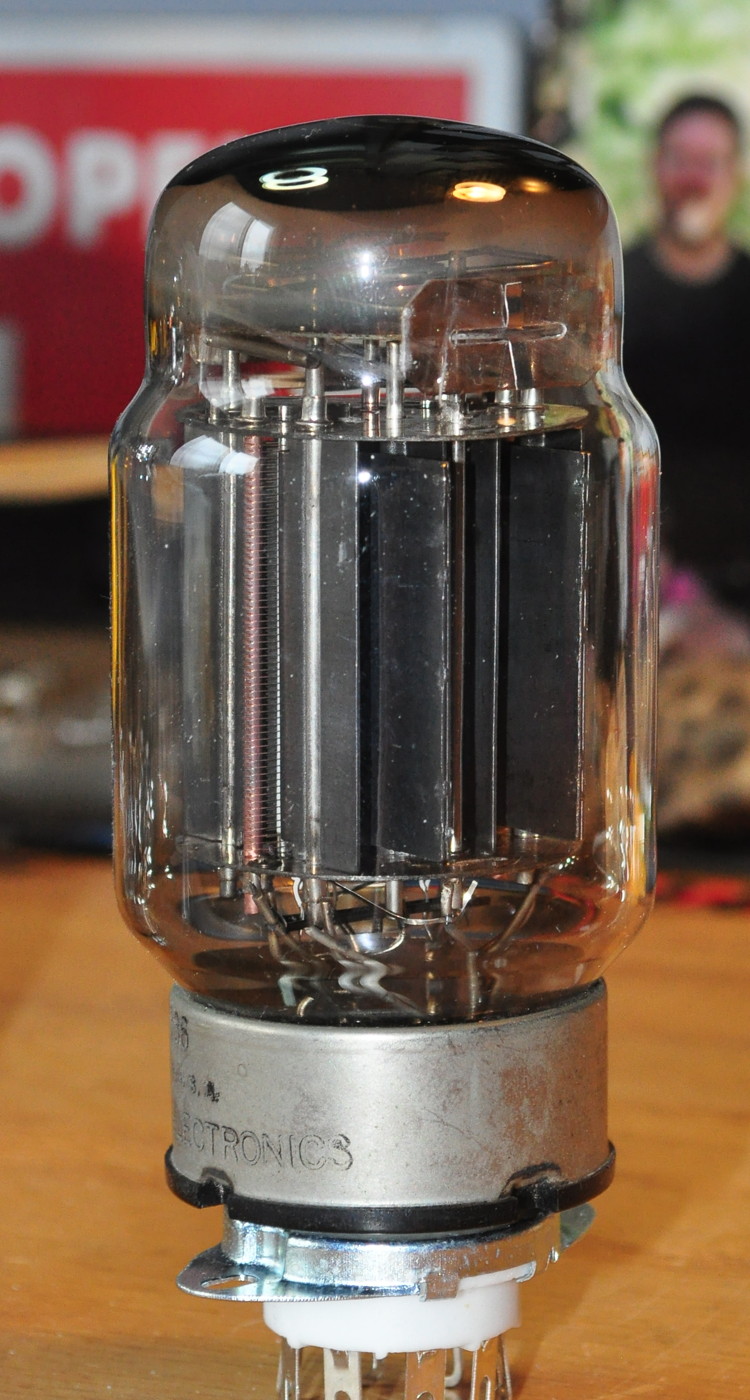 And the newer 6336A with zirconium coated graphite plates shown here.
 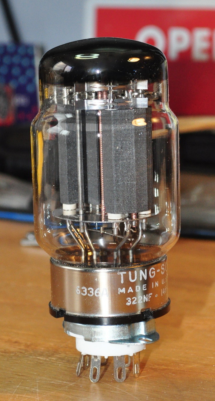 In 1965 Tung-Sol announced a 6336B which had the same ratings and maximums as the “A” version but lower grid leakage. However, at that time many military power supplies were switching over to solid state regulation and it is unclear how many 6336Bs were actually produced.
I have found good and “no so good” tubes of both types; with some tending to be a little microphonic. I would say take what you can get and see how they work. The amp is designed to work with any 6336 tube. I wouldn’t worry about matching as the pass triodes work independently. Unless the imbalance is really extreme you’ll probably not notice any difference.
Great article Matt,
I hope you consider writing a book in the future.
Sounds like a good design to me