
Just An Idea
So for quite some time, actually since first designing a 300B amplifier back in 2010, I have been playing with the idea of designing a nice intermediate power (5 to 10 watt per channel) SET amplifier. But I didn’t want to revisit the 300B or 2A3 DHT power triodes, I wanted something different and something that didn’t have the obvious drawbacks of the DHT tubes.
After some investigation I finally settled on a big dual pass triode, the 6336. This tube has several features that that provide distinct advantages over the old DHTs. These include:
1. Unipotential Cathode – This is probably the biggest advantage of this tube. With DHTs there are all kinds of requirements for heater circuits for high fidelity audio reproduction. The fact that the 6336 has an isolation between the cathode and the heater means the heater circuits are simple and introduce no hum into the amplifier. This is a huge benefit.
2. Dual Triode Structure – This is an additional benefit in that only a single tube is required for stereo amplification. This greatly simplifies layout and wiring. It also means only one filament supply is required. Some might argue that having both power triodes in one envelope might lower reliability. However, given that the 300B is an old design meant for usage in racks of telephone equipment, and the 6336 is a more modern design intended for hard physical mobile environments, a single 6336 should actually work out to be MORE reliable than two 300B tubes.
3. Rugged Construction – The 6336 is a ruggedly constructed tube with a hardened glass envelope, internal vibration isolators, heavy duty supports, and a modern octal base. While the old DHTs can be rather fragile in their construction, the 6336 is a heavy duty tube meant for tough use including a 720G shock requirement, a 10G low frequency vibration requirement, and a 5G high frequency vibration requirement. Additionally, the eight pin octal base is just a much better solution for large tubes than the old four pin bases used by the 300B and the 2A3. The guide pin provides significant stability not available on the older socket styles improving physical stability, long term electrical contact, and overall performance.
The Electrical Design
The first thing I did was to start performing some pencil and paper load line design work. After comparing the power and distortion characteristics for several different loads, I finally settled on a 2.5kΩ plate load in a cathode biased configuration. This resulted in the following power stage load line design.
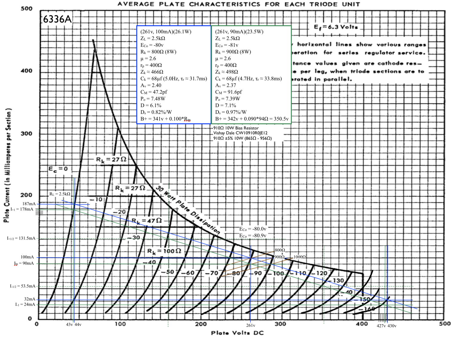
Since I didn’t have a full design I preserved two distinct design points at this stage. The tradeoff between these two being almost entirely DC load current verses peak distortion.
The next step, since I have never built with this tube and didn’t have any feel for how it behaves, was to perform some initial prototype testing. Now, there are some challenges to designing with big power triodes. Typically, these types of tubes have very low power sensitivity. This means that it takes a large swing in drive voltage to produce the output power.
In the past I have approached this problem using high gain triodes and choosing a bias point optimized for output voltage swing. These design were all predicated on using a single driver tube for the amp. For this amp I decided on a different approach. I decided that a cascaded set of low gain triodes could provide better performance. The driver I developed was a cascaded 12AU7 design discussed here (Brassboard Prototypes) and here (SET Driver Revisited). Here is the prototype driver gain response.

This driver has high gain, large output swing capability (over ±100v), and good distortion characteristics. So using this prototype driver, I proceeded to perform some prototyping. Here’s the prototype sitting on my bench.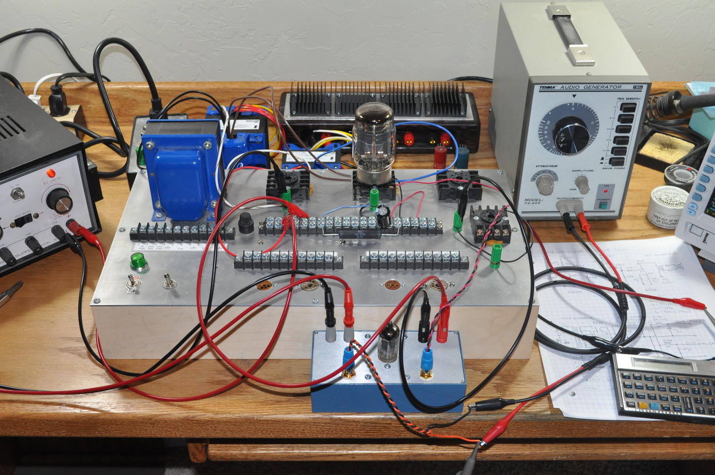
The prototype showed that I could get very clean performance up to 6.3W output and acceptable performance up to about 8W. With this information in hand, it was time to start my build.
With the prototype performance in mind I finalized the electrical design for the amp. Here is the final signal stage schematic.
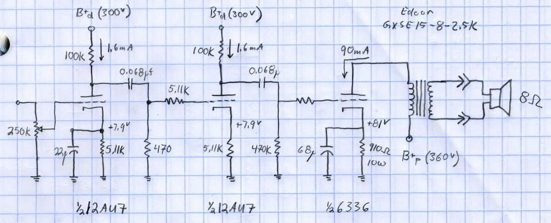
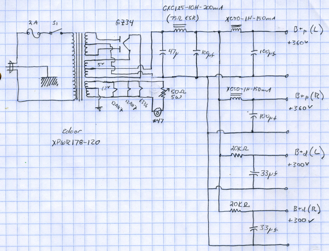
This design uses both triodes of a 12AU7 as a driver for each channel feeding a single triode in the 6336. Due to the high power stage DC current, I decided to go with a slightly larger output transformer, the Edcor GXSE15-8-2.5K. I felt that the larger core of this transformer would provide better magnetic saturation headroom than the 10W version. I managed to find an appropriate stock power transformer for this design. This was a challenge due to the massive 5.6A power draw for the signal tube filaments. I finally settled on the Edcor XPWR178-120. Here is the final power supply schematic.
I think I should mention a final design challenge with using this tube; heat. The filament load for the 6336 is 31.5W and my chosen design point dissipates 23.5W in each plate. This puts the total heat load in the the 6336 at 78.5W. This is actually a quite significant heat load to be concentrated in one tube. Now the tube itself is designed to handle this without issue, but it gets fairly warm. In my design the 6336 has a steady state tube surface temperature of about 274°F (135°C). This is not an amplifier which should be placed where small children or curious pets roam.
The Build
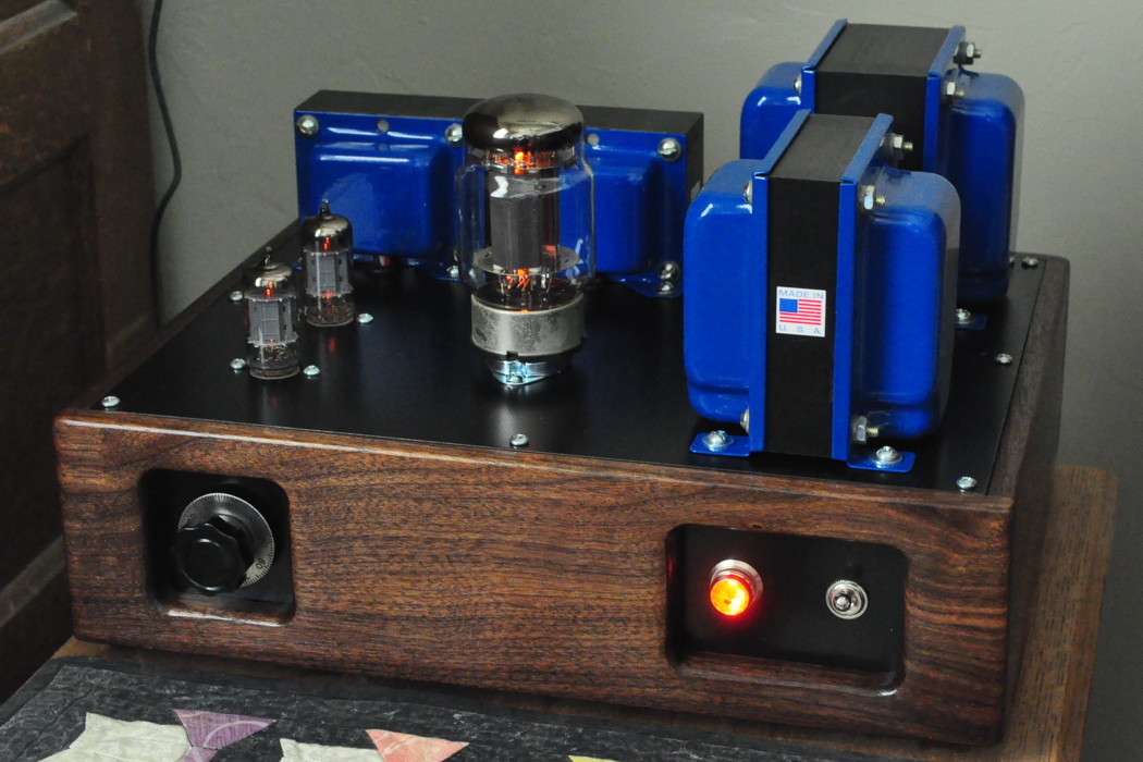
With the electrical design settled it was time to do some physical layout. For the physical design, I wanted a look that hinted at the old tube equipment from the 1930s and 1940s. The design elements include dark walnut for the chassis, black metal plates, an old numbered radio knob for volume control, a jeweled power indicator, and an old style toggle switch.
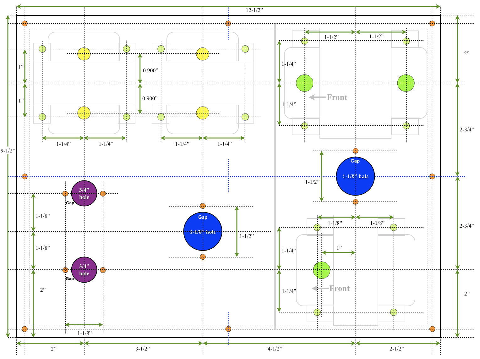
The layout for the top plate is fairly compact. Here is the layout drawing showing all the positions of the components on the top plate.
Overall the design came together nicely. The internal layout is not too cramped despite the amount of circuitry under the plate. Here’s a look at it.

Here are photos of the assembled amp from the front and rear sitting on my work table.


The overall look of the amplifier is spot on. The dark walnut and front panel controls give it just the “old time” appearance for which I was looking.
The Testing
Here is the end to end gain of this amplifier.

The very good low end performance is due to a combination of, the 22µf bypass capacitor on the first stage of the driver, the 0.086µf coupling capacitors, the very low output impedance of the 6336, and the healthy input impedance of the 15W transformer.
The high end roll off seen here is due to the very large (10kΩ) grid stopper resistor used on the 6336 triode. The response is only down about 3.9dB at 20kHz but someone with very good high frequency hearing might notice a falloff. This was used due to some initial concerns about the stability of the overall signal chain. However, after testing, I am confident that the grid stopper could be reduced to just a few kΩ which would restore the full top end response out beyond 20KHz.
Impressions
This is a big powerful SET amplifier. It is warm, detailed, fast, and has an excellent sound stage. The Beast has handled just about every type of music I’ve thrown at it with ease. Jazz, rock, opera, classical, choral all really come through with incredible detail and staging.
But the amp seems to truly excel at big classical scores and choral music. many amp have trouble with this type of music and become muddled; but not this one. The complex nature of these scores really lend them selves to an all triode signal chain. And The Beast does not disappoint!
This is a great project. It really delivers big powerful sound without losing the detail and quickness of the little triode SETs. If you’re looking for a somewhat more challenging project, I highly recommend this one. I think you’ll really like it.
Hi, Thanks for your awesome projects, I happen to have some NOS Reytheon 6336A around and planning to build your amp, but I have a question; In your loadline drawing the bias point is at around 261V but in the schematics the B+ is at 370V, can you please explain it to me?
Thanks
Yes, that’s correct.
The plate current through the tube flows through three elements, the output transformer, the tube itself, and the cathode bias resistor. In this design the plate current is estimated at 90mA. This means that the output transformer will drop approximately 8V (90mA * 94Ω ≈ 8v) and the cathode bias resistor will drop 81V (90mA * 900Ω ≈ 81V). So if the plate voltage needs to be 261V then the B+ needs to be the cathode bias resistor drop, plus the plate voltage, plus the output transformer DC voltage drop, or 81V+261V+8V=350v.
The final B+ voltage for the power stages on the schematic is 360V. This is only a ≈3% overshoot which is more than close enough. You can include a small dropping resistor in the power supply to get the voltage back down to exactly 350v but the actual quiescent operating point of the power stage is actually more important.
Thank you so much for the answer.
Another question if I may; is it possible to use 6SN7 in place of 12AU7 in both preamp stages? If yes, what values for anod and cathode resistors and caps do you suggest?
Thanks again
Sajad
Yes you can. Wire it with identical component values except, increase the first stage bypass capacitor to 47µf. You must not omit the first stage bypass cap or the upper end frequency response will suffer.
It will produce a more sensitive amplifier. The overall gain of this chain will be about 3dB higher.
Thank you Matt. ME too i definitely prefer 6SN7 than ECC82…. There is something about the sound of 6SN7,6SL7 and 6J5 Nos american tube that i like more than our small ECCxx double triodes. And Althoug i have hundred of excellent nos 9 pin EU double triodes, i like to use octall bases. So thank you for the info above, it was very useful in deciding to build this fantastic SE. And, logically, thanks a lot for all your projects! They are all really great
Thank you so much, I can’t grt enogh of your website, this is my third project from your incredible designs.
oi matt estou com um problema e gostaria de um aajuda sua se possivel o resistor de catodo da 6336 tentei todos os valores disponiveis e estao esquentando muito com poucos minutos de operaçao ate mesmo subindo o resistor com disipaçao de 50 a 100 w ainda assim esquenta pode ser um problema no tubo talvez??? a unica soluçao foi por resistores de catodo de 10 a 15 k so que o volume fica muito baixo nao sei se chega a 2 w de potencia nesa configuraçao , agradeço se puder responder
>Hi Matt, I have a problem and I would like some help from you,
>if possible, the cathode resistor of the 6336 has tried all the
>values available and it is getting very hot after just a few
>minutes of operation. Could it be a problem with the tube
>perhaps??? The only solution was to use 10 to 15 k cathode
>resistors but the volume is very low. I don’t know if it reaches
>2 w of power in this configuration, I would appreciate it if
>you could answer
The cathode resistors on the power stage dissipate about 7.4W of power. Even the large resistors I used get fairly hot. Between the conducted heat from the power tube itself and the power dissipated in the cathode bias resistors things get very warm.
I don’t know what you mean by very hot (estão esquentando) but it is expected that they will be warm. The maximum operating temperature for the resistors I used is 250°C. I would be surprised if they ever got close to that hot. But they will definitely always be far too hot to touch.
I suggest you go back to the 910Ω/10W resistors and calculate the power dissipated in the resistor. Measure the voltage across the resistor which should be close to 80V and calculate the power with the formula P = (V*V)/R with R=910Ω. If it’s less than the power rating of the resistor, you should be fine.
I talk about the heat load from this amp at this forum post. https://diyaudioprojects.com/Forum/viewtopic.php?f=9&t=5896&start=1
Hi Matt,
I am putting together the transformer/choke order and realized that it looks like edcore does not make the XC50-1H-150mA anymore. Would you be willing to recommend a suitable substitute?
Thank you for the help I really appreciate it!
The closest direct substitute I know of is the Triad C-24X inductor. It is however, quite a bit bigger than the Edcor unit I used.
You could also use a Hammond 158SA or go to a 2H inductance with the Hammond 157R.
Hey Matt,
Thank you for getting back to me, sorry to for the follow up question, can I use any of these substitutes without additional modifications to the circuit?
Yes, any of these can be used without modification to the circuit. They’ll all do the job admirably.
Hello Matt.Currently working on the beast. Just wanted to make sure: Is the center tap(yellow/white )off the 5v supply the positive for power supply ? Thank you
Yes. That is correct.
Heater is 5A. What gauge is the heater wire?
The heater wire to the 6336 is 20 gauge (diameter 0.032″ or 0.813mm). This is more than sufficient for the load in this application.
Before the internet goes on the war path, please let me explain. In my design, the heater wires to the 6336 are separate from the other 6.3v heater wires going to the signal triodes. There is about 10 inches of heater wire in the 6336 heater circuit. The 20 AWG wire I used has a resistance of roughly 10.15Ω per 1000 feet. This means that the resistance of the 10″ of wire is about 8.5mΩ. The voltage drop in that wire at 5A is ≈42mV. The power loss into the wire (which is radiated by the wire as heat) is ≈210mW or roughly 1/5th of a watt. Neither the voltage drop supplying the tube filament nor the very small power loss in the wire is enough to matter.
I hope this explanation helps clear things up.
Thank you.
I had thought that the wire should be the same as the transformer winding. Which should be about 1.5mm in diameter for 5 ampere.
So its different then.
Edcor terminates the XPWR178 transformer with 18 gauge (diameter 0.040″ or 1.02mm) leads on all secondary windings. This is slightly heaver than I used but would also bee acceptable.
Wire 1.5mm in diameter (≈15 gauge) is overkill for a 5A load inside a chassis.
Thank you Matt for such a fantastic and simple SE 6336 amplifier design.
I have finished my version 3 months ago and have been listening to it daily since I finished the last soldering. It is my first experience with a triode system and no negative feedback.
I can only say that it is an addictive sound.
Greetings from Chile.
https://flic.kr/p/2mhgo3h
I’m glad you like the amp. It is one of my favorites as well.
Hello, here I am again, a few months after I experimented & enjoyed building the “Marblewood” which was a great first project !
Today, I just completed the 6336 build,
I grabbed my tester, made the measurements, they were (almost) spot on.
It was time to take a deep breath, and turn the amp on : ……………………………?
Wowwww ! My living room instantly got bigger, the sound stage is huge, the music is transparent , full of details and really mesmerizing. The bass is firm & so realistic. When listening to tracks from musicians I had seen in concert, it was the closest thing I had heard so far to being in the concert hall.
One of the best amps I ever listened to.
On the Mains transformer I went about 40% up from specs, on the output transformers I could only find 25W units so there is lots of headroom… I used PIO for the signal path, & I settled for a 4,3k grid stopper on the 6336.
Again a very sincere THANK YOU 🙂 Matt, for helping us out, we, the lost souls who still don’t know how to calculate their own …
Even my wife who was complaining about “yet another amp…pfff” said she loved it, and she suggested we use the amp as a toaster, to make the whole project more practical. (you weren’t lying about the heat dissipated by the 6336 !).
My next thoughts are drifting towards the East: a SET 6S33S… with 6E6P drivers. I bought those nice vintage tubes on ebay, they are now looking at me from the workbench…
Christophe.
It’s always great to hear about another successful build. Now you can start doing some listening comparisons between the SE-UL and SET topologies. Watch those 6C33C-B / 6S33S-V triodes. Even in single cathode mode they are seriously current hungry. Can’t wait to hear about how it goes.
Hi Matt, first, thank you for sharing your work in such detail. Your methodology of getting things designed in the EE way is a great inspiration for the non-EE hobbyists like me. Some years ago I came across you 4S preamp and I settled with a non-tube interchangeable preamp using 12AT7 SRPP rigged. It all started with the 4S design. Last year I started studying your 6336 SET. Finally, my 6336 SET is almost done. I call it Beast Jr. as it has a smaller presence in terms of size. The design I am using is a scaled down version of yours with 10W OPT and only one 2H choke. PT is the same as yours. B+ and B++ are achieved with RC filters. Did try to use GZ34 bought at TubeDepot as rectifier tube but it arched. Tubedepot did not respond to my messages to them. I guess their warranty is 3 months and this GZ34 was purchased in Aug. 2020. Too bad. I did add diodes on the rectifier tube socket hoping to tame the arch. It did not help.
I was forced to use one of the older 5U4GB tubes at hand. Fortunately it did not arch. The only drawback is a lower B+ of 348V which is about 10V lower than using GZ34. The other drawback is a very fast B+ charging time at turn on. During testing the half finished amp, I found the frequency response is exactly the same as yours with high frequency roll off from 12K- 20K Hz. However, I found the sound kind of dull to my ears. So, I changed the 6336 input grid stopper from 5.1K to 1.2K ohm as you mentioned in your analysis. It helped but not too much. Then I tred to add some local NFB from the second stage 12AU7 output to input. It worked but with gain loss. Moreover, I would like to have a SET without NFB. I had one such SET made some 8 years ago using 6EM7 which was without NFB. Anyway, I tried to add cathode bypass capacitor in the 2nd stage 12AU7 section, with 1uF, 10uF with some NFB. All were not satisfactory in terms of sound and gain loss. Finally, I added a 22uF cathode bypass cap in the 2nd stage 12AU7. It really boost the frequency response to -0.95dB at 20KHz and -3dB at 32KHz. Very happy with the result.
Here are my questions:
1. With this cathode bypass cap will it affect the damping factor?
2. Is the possible cause, a loaded down 2nd stage 12AU7 by the 6336? (A fully bypassed cathode reduces the output impedance of the 2nd stage 12AU7?)
3. I did all the calculations using an Excel model. It seems like the input impedance of the 6336 would have to be around 480pF to generate such result. I could not measure it due to the unknown stray capacitance of the wire and in the other parts of the network. Does it sound right?
Will do more testing regarding total harmonic distortion and intermodulation later. Your advices will be greatly appreciated. Best regards. David Kuo
Hello matt,
Just wanted to drop in and thank you for an awesome amp. Finished the build a few days ago and it is by far the best sounding amp I’ve ever built. I made a couple of mods, mainly a DC heater supply. Was wondering what you thought of possibly replacing the 12au7 with the Russian 6n6p tubes. I have a few on hand and have heard a lot of good things about them.
Anyway thank you, love my new amp.
I’m glad you like the amp. It’s kind of a complicated build but worth the effort in my opinion.
The 6n6p (6H6П) is not a drop in replacement for any of the 12A*7 US/UK dual triodes. It has a different heater pinout (no center tap & 6.3V between pins 4 and 5) and the design center values are a little different from the 12AU7. In some amps you might be able to make the substitution with a heater rewire, but probably not in this one. The cascaded high gain driver circuit has been optimized for the 12AU7 and likely wouldn’t behave as well with a different tube.
I actually was thinking of including a switch to change the heater wiring to go toggle between the two tubes. it would involve a lot of work so I decided against it. The amp just sounds too good to mess around with it. Sometimes the enemy of good is better I guess!
Matt,
What would be your thoughts on using two of these 6336 SET amps as a mono block bi-amping kind of set up. Meaning that I would move the individual volumes out of them and make a volume control input selector like your previously done volume control project. Then use the stereo outputs of each amp to “bi-amp” a two way speaker with high and low pass filters. What would be the pit falls impedance wise of splitting a left or right channel into the stereo inputs of each amp? It’s not really a traditional mono block set up but my mind is always spinning. And I could make these more of a true mono block set up if I built a second power supply and just did one channel each.
Just tossing around ideas because there isn’t much to do these days. Hope I got the question off in an understandable way, and I haven’t even had my first scotch yet. Just wondering your thoughts and suggestions on all of that.
This would be a possibility. Due to drive characteristics I think I would have dual drivers with the frequency selection filters between the two stages. Then I’d use one driver for each channel (HI/LOW). I guess that this would make them bi-channel monoblocks. It’s an interesting idea.
Matt,
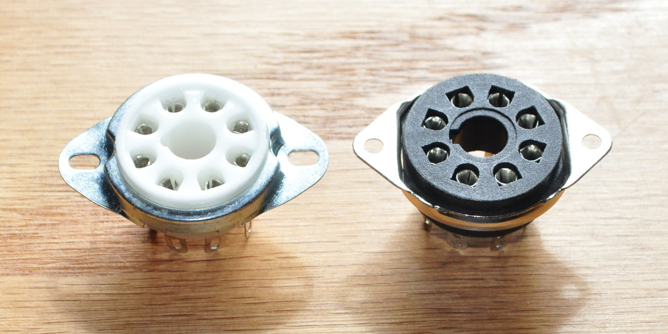
Is there any special consideration to the tube socket used and the placement of the 6336 because of the heat that it dissipates?
Yes. As documented in this post, the 6336 generates a lot of heat which can damage components. You should definitely use a ceramic socket like the one on the left in the photo below, and not one of the black plastic ones like on the right.
There is also a discussion on the forums here concerning heat. Read down to my next post where I decided that the temperatures were really ok after all.
Thanks Matt.
Hola Matt, estoy pensando en construir su amplificador SET 6336 y quisiera preguntarle si la conexion de la fuente de alimentacion positiva que va a la toma central de la salida de 5 + 5 vca es correcta.
Nunca lo habia visto conectado de esta manera. Normalmente van el positivo (+) va conectado a un extremo del catodo. Por favor, le agradeceria que me confirmase que el circuito de alimentacion es correcto. Muchas gracias por su ayuda y perdon por mi ingles. saludos desde españa.
————-
Hi Matt, I am thinking of building your SET 6336 amplifier and I would like to ask you if the connection of the positive power supply to the central socket of the 5 + 5 Vac output is correct.
I had never seen him connected in this way. Normally, the positive (+) is connected to one end of the cathode. Please, I would be grateful if you could confirm that the power circuit is correct. Thank you very much for your help and sorry for my English.
A greeting from Spain
Yes, the schematic is drawn correctly. This is actually a better way to load filamentary cathode rectifiers. It was common in the early days of tubes and is still the reason for rectifier filament center taps on these transformer windings. If you are uncomfortable with this approach, you can use pin 8 on the rectifier socket instead of the 5v winding center tap.
Thank you very much for the information.
I will do it as you say.
my best greetings
Hello,
I’m quite new to tube projects, but a few days ago I successfully completed the 4S preamp design and now I’m looking for a low-distortion hifi amp for classical full-orchestra music listening in a flat. This quest brought my attention to this project, but I have a great problem finding 6336 tubes in Europe. Are two 6080’s an option here? If so, do you have any design tips/advice on adjusting the circuit for such solution? Will the power be significantly lower with those replacement tubes?
First, I understand that 6336 tubes are on the “hard to find” list. They are actually more common in the United States because they were widely used in equipment for US Navy vessels so there are a lot of surplus tubes available. I strongly recommend against substitutions in the circuit. I have had luck finding the 6336 tubes on Ebay.
However, this is really not a suitable project for a first power amp. While the design is very good, the big tubes are a little temperamental and the circuit more complicated than most. If you are looking for a first power amp type project I would actually strongly recommend the MarbleWood Amp design. Using 6W6s in the Marblewood circuit gets you within 2.9dB of the 6336 at peak power which is not enough to notice in most environments. It is also a well matched amp to orchestral and symphonic musical scores.
I hope this helps.
Thank you very much for your fast reply! I shall go along your suggestions then.
Hi Matt – there is a “coupling” resistor between the 2nd driver stage and the 6336 for which no value is marked on the schematic. Is it also 5.11k?
Thanks.
That’s the grid stopper for the big triode. I didn’t put it on the origonal schematic because it was something with which I experimented.
The power tube Cm at this bias point is ≈92pF and Ro of the second driver stage is ≈12.5kΩ. Under these conditions I would think that something in the order of 5kΩ would be appropriate. If you have a few extra 5.1kΩ resistors I would use them in the power stage grid-stopper position.
Grazie!
Interesting coincidence that in all your photos of this amp, the 5AR4/GZ34 rectifier is never visible! I started to wonder where you’d put it, then saw it on your CAD layout drawing, hiding between two transformers.
🙂
Hi Matt,
Wow, awesome build. I also liked the picture of your very well organized custom work bench. Looking at a picture of the build I noticed a potentiometer to adjust B+, but couldn’t find it in the schematic.
Terry; Sharp eyes! Good Catch.
If you look down through the comments, I explained the B+ adjustment scheme in a response to Wade back on the 27th of September 2018. You should take a look at that response. Thanks.
Very intrigued with your design, and am collecting the parts to give it a try. Would you know how one would add a line out to this circuit? Thanks for sharing this design. Nice work!
Very intrigued by this design, and am collecting the parts to give it a try! Would a line-out work with this circuit, and how could that be implemented? Thanks for sharing. Nice work!
Randy; This amp is a line level input amplifier needing only about 0.8v RMS to drive it to full power. As such, any line out would likely be connected directly to the inputs. You could include a pair of cathode followers from the inputs to buffer the line outputs. I would recommend using the cathode follower from the circuit posted in this thread.
Perfect! Thanks!
Matt,
I’m new to building projects like these and am looking forward to sourcing parts and building this. My question is maybe a noob question but I have a question on the grounding. I noticed your chassis grounded right to the mains ground. But are the other grounds all signal grounds isolated from the chassis. I want to avoid ground loop hum and was wondering if this is the idea. Any direction and some of your expertise on grounding would help be greatly appreciated.
Rather than getting into a long discussion, I have made a blog post here that should answer your questions. Let me know if this helps or not.
Thanks Matt. That was informative and cleared up a lot for me. I’m looking forward to see how this comes out.
would a paralleled 6336a tube require a1.25k output transformer.please reply asap.regards don moffat
Well, technically speaking, a 1.25kΩ load would duplicate my load line with twice the current (assuming the same effective bias). However, there is a lot more to the decision that just paralleling sections. The design would really need a complete reoptimization.
There is also the fact that these big regulator pass tubes really don’t parallel very well. Most manufacturer recommendations for pass tubes said that for audio amplifier use, to run the elements in push-pull if you wanted to use both elements in one power stage. They also recommend always using cathode bias with separate cathode resistors on each leg. As to paralleled sections with these tubes, as the edge of the map says. “Beware! Here there be Dragons!”
hi matt,what output transformers would be required for 6336a valve with both sections paralelled.could you please help me with this query.regards don.
I really appreciate the sharing of this extremely detailed, well-thought-through information on this build! I have been into audio on and off for decades, and built and owned some very good equipment, but, until very recently, thought that single-ended amplifiers might just be a bit of an unsubstantiated elitist fad. BUT then I picked up a TubeCube 7 EL84 SE to give to my son and I was just plain astonished beyond adjectives at the nuances that I was hearing in music that I had not heard before. Which leaves me wanting to build something similar, and I am intrigued to see if triode SE will let an amplifier “get out of the way: even more.
A question – there is another tube, related to but distinct from the 6336- the 6528, which has nearly all of the same design and ratings but that has substantially higher gain. Do you see any barriers to me trying to use a version of your circuit with the 6528 (maybe with less gain at the input stages)? Any obvious drawbacks to going with the 6528? Any tips on doing that sort of adaptation? Thanks very much for your suggestions
When I was designing this amplifier I looked seriously at the 6528. However, it was not a nearly as good a performer as the 6336. The Rp is significantly higher than the 6336 and this causes problems with low frequency response. In addition, in order to get the distortion under control, the tube requires a higher plate current and this drives power supply design. And finally, with the much higher amplification, the cascaded driver used for the 6336 would have far too much gain.
So, in short, yes you can use the 6528 as a power tube. But it necessitates an entirely different design. I have portions of that design which I did as I was developing the early concepts for the Beast, but it’s not a finished product. And it has not been prototyped. I can email you the 6528 bias points at which I was looking. But the driver would be a more traditional design and the power supply would have to be designed from scratch.
Hi Matt- thanks very much for your response. The more I have looked into things the more I think I will go with the 6336, and your design, rather than the 6528. The 6528s seem more scarce anyways and the few things I found about people trying to build amps with them, sounded like they had frustrating and lackluster results. I am starting to scheme what particular ways I may go about building this (I am probably going to use a pair of 7193/6C22 tubes in the driver stages- they have very similar characteristics as a 12au7 and are affordable and get good comments for their sound) and I am really excited, although, with other responsibilities, it may be quite a while before I have it completely built. Thanks again for sharing your knowledge and experience!
Hi Matt,
Thanks for sharing your great design. I’m collecting parts now to build your amp. I have a set of opts that I hope can be used to save a few bucks. The specs are:
Class : Single ended, 8C-CORE design Primary impedance :0-2.5K Ohms
Primary DC resistance :150 Ohms
Primary inductance: 11H Secondary impedance : 0-8-16 Ohms
Secondary DC resistance :1.2 Ohms
Maximum voltage:2000v
‘Maximum wattage: 32w
interleaving winding: 4 layers Frequency range : 20–35K Hz
Maximum DC current : 80Ma
Tube application : 300B The induction plates is amorphous C-CORE, come from UK Size : 86X88X75(MM) Net weight : 4kg / pair
I’m concerned about its 80 ma capacity. Can I safely use these opts in your amp? If not can the amp be modified so they can be used.
Regards,
David
These outputs look acceptable except for their primary current limit. Clearly they are not sufficiently gapped for the 90mA of bias current. if you want to use these, I would recommend increasing the power stage cathode bias resistors to 1000Ω, like one of these RS0101K000FE12 or 40F1K0E, and reducing the B+ by about 8v to 10v. This is so that your steady state bias current falls below the 80mA limit specified for your transformer.
Hi Matt.
I thought these tubes were similar to 6550 or kt88s. Didnt realize they were dual triode.
I have a pair of 6336 and 6336a. I find 6336 look more solidly built and heavier than 6336a
Why cannot this amp be used with a preamp? How will you be able to play records and other analog sources?
Thanks
This amplifier can be used with a preamplifier when required. However, the sensitivity is such that it only requires about 3/4v rms to drive it to full volume. Most line level sources (iPods, computers, phones, cd players, ceramic cartridge phono players, etc.) will easily drive this amp without a preamplifier. The only place you might rally want a preamp is for RIAA equalization and preampfification of MM/MC phono players.
Dear Matt,
Thanks for your design, after having implemented a few PP amps, I would like to build a SET. Your design fits my build, I like this large dual-triode !
I do have a power tranny left over from a previous project, it was build wrongly for the other project and I look forward to use it in this build. However, it is not center-taped so I would build a full-wave rectifier using SS diodes. Before I try simulations in PSUd, could you please let me know what the total current draw is for both channels, on the B+ ? From the schema, I would assume twice 90 mA, so a total of about 180mA, right ?
Thanks again Matt !
Nominal draw for both channels is 186.4mA {2*(90+1.6+1.6)} not including bleeder resistor draw. And remember to use UF4007 diodes.
Looks like the edcor chokes are no longer available. Would any changes need to be made to use the slightly higher current XC63-1H-200mA instead?
Yes, I’m aware that the fine little XC50-1H-150mA is no longer available. My current favorite choke for this job is the Triad C-24X 1H, 240mA power choke. They are essentially the same size and performance as the Edcor XC63-1H-200mA. However, whereas the Edcor choke is $22.40 USD on their website, the little Triad choke is currently listed at $9.78 USD at Mouser Electronics (https://www.mouser.com). I generally buy these in lots of 6 to 10 when I need them.
Matt,
In this design I notice you’ve orientated the output transformers at 90º to the power transformer. Is this for the finished look, or to minimize interaction between them?
This was done for the finished look and to maximize the usable space on the top plate. Given the chance to build another one, I would probably spread out the top over a somewhat larger area.
Hey Matt!
I’m sourcing the parts for the ‘Beast’ now, and can’t wait to build it. Did you put an input pot on this design because the input sensitivity is such line level devices like phones/CD players will easily drive it? Or, do you recommend a preamp? Thanks in advance!!
On this amp the power triodes are biased to about 80v. The cascaded driver gain is about 37.7dB or 77v/v. This means that it only takes a signal level of about 1.04v peak or 732mV rms to drive it to full volume. Because of this it just made sense to put a volume control up front. A line level input, an iPod, or portable CD player should all drive this amp easily.
I do NOT recommend a preamp with this amplifier unless it is relatively low gain. Power stage overdrive could be an issue with a preamp unless your input signal level was very small.
Makes perfect sense. Thanks for the response and numbers. Awesome!
What a great design! I think the 6336 is maybe my favorite tube and I have played around with some designs to use it for audio but nothing serious. I will definitely give your design a whirl! I noticed that you have a knob for increasing the B+, could you tell me more about that?
The control you see in the build picture was an adjustment knob I included to fine tune the B+. Not included in the schematic, but built into my initial PS build, was 150Ω of fixed voltage drop resistance (≈28v) and the 100Ω potentiometer you see in the picture. The final potentiometer setting was 71Ω when I sealed up the chassis (≈13v). So my final build contained just enough drop (≈40v) to place the B+ at exactly 350v. Now without this the B+ would only be 11% above the design point which would have been more than fine for operational purposes. And the Edcor XPWR178 has a 3A 5V winding so any of the big octal rectifiers could be used to play with the B+ a little. However, as this was the first time I built an audio amplifier with this tube, I wanted to be able to see how it performed at the exact design point. These PS features are not required for building this design so I left them out of the description.
Does this answer your question?
hi matt,my name is don moffat a friend of mark Houston.ihave built amps from acouple of your designs,they sound very good I happen to have some 6336 tubes I was going to build a pp 6336 amp fron a glass audio design.i have now decided to build your current design for 6336 tubes.will contast you when completed.regards don moffat.
I’m glad my other designs have worked out well for you. I hope this one does as well. Pease let me know how it turns out.
Nice-looking amplifier do you think it would benefit from The 20/20 edcor output Transformers, I was initially thinking of building the 300b amplifier but the heaters on the 6336a seem to be a little bit simpler. Does the sound compared to the 300b somewhat? Can’t find too much information on the internet about the sound of the tube. Any thoughts would be appreciated.
Thanks. I really don’t think this amp needs the CXSE series transformers. With a 2kΩ grid stopper on the 6336 this amp will deliver a full 20Hz to 20kHz response without a problem. Even at full output there is no sign of any type of magnetic saturation in the transformer. I went with the GXSE15 specifically because I wanted the larger core to avoid any core issues. But even with the lower inductance of the primary (as compared to the CXSE units) the Rp of the big triode is low enough that the low end response is no problem. I’d recommend sticking with the specified transformer. I suspect that some of the “nimbleness” of the amplifier would be compromised with the bigger unit.
As to comparing it with the 300B, that a tough question. I don’t currently have a 300B amp with which to do a realtime comparison but I have had a couple in the past. The first caveat I would give is that the “sound” of an amplifier has as much, or more, to do with the design than the tube. That being said, I would put this amp up against any 300B I’ve ever heard in a blind, head to head comparison. I will say that I think this amp is a little warner than most of the 300Bs I’ve heard. I think that’s due to the slightly higher 2nd harmonic in this tube. But it is a very easy amp to which to listen. And there is no hint of hum of noise in the output.
I hope this helps.
Thanks for the quick reply can’t wait to get started on this amplifier probably start after the holidays sounds like this amplifier will keep me warm in the winter thanks again Merry Christmas and a Happy New Year