
A Different Approach to “Universal”
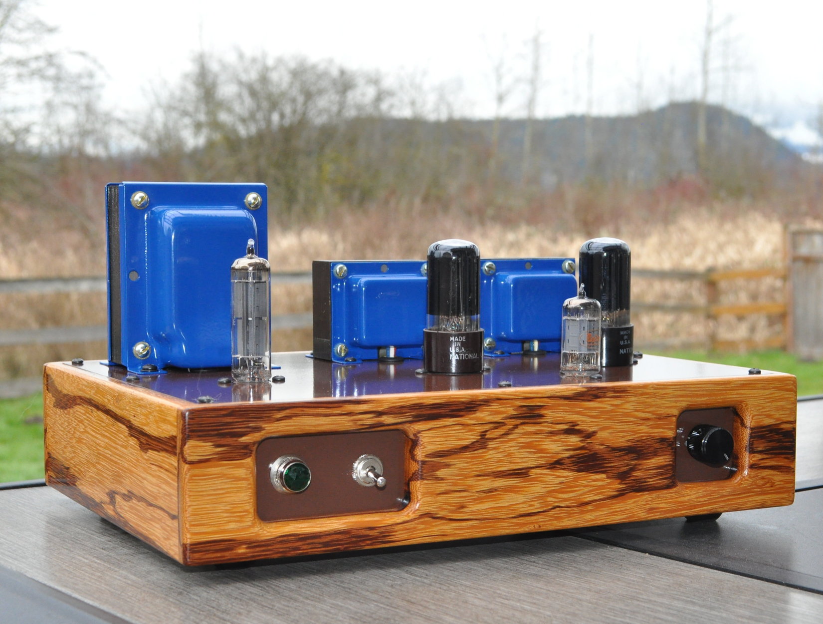
This amplifier started out with a stroll through a woodworking store in Oklahoma City, OK. What caught my eye was a single plank of a species of wood with which I’d never worked, “Marblewood” or zygia racemosum. The wood was expensive so I bought a single piece six inches wide and four feet long. Thus was the “Marblewood” amp born.
Now that I had the wood, I needed an amp to wrap it around. At his time I had just finished the rewire of the Lacewood amp using the information I had from the 6V6 bias optimization study. While doing that project, I thought that I should really design an entirely new 6V6 SE design specifically targeted at someone doing their first major tube amp build. This seemed like the proper opportunity to give it a try.
The Electrical Design
There were a few goals I had in mind as I started this design. Since it was targeted at a first time amp builder, I wanted to keep it as affordable as possible but still produce a really nice product. This meant a simple, but good quality, power supply, a minimalist topology to the amp circuit itself, and an elimination of anything that didn’t need to be there (within reason of course). I also wanted something else; I wanted the circuit to be versatile. I realized that a first time builder might like the ability to change things out, maybe try different tubes and explore the changes in sound that makes. So I ended up with the following schematic for the amplifier.
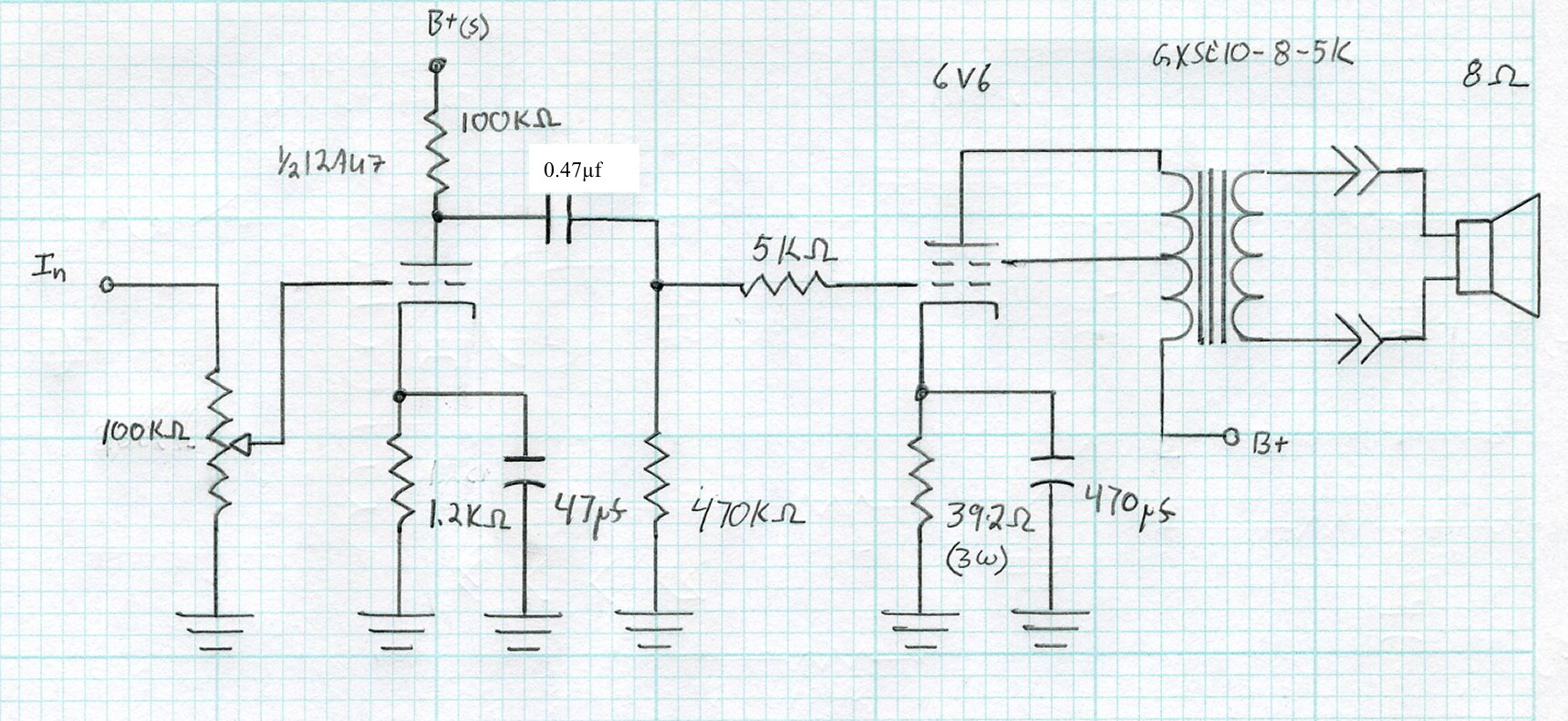
This deceptively simple design has a couple of things going for it. First it uses a 4S Universal preamp circuit as a driver, with the volume control moved to the front. This means that the 12AU7 driver tube can be substituted for a different sound and gain level with any of the following tubes: 12BH7, 12AV7, 12AY7, 12AT7, 12AZ7, and 12AX7. This is a total of seven common driver tubes which can be used with no modifications to the amp whatsoever.
Second, it uses the optimized bias point for the 6V6 power stage. This produces good results across a variety of B+ voltages with the 6V6 beam power tube. But as a serendipitous benefit, this bias resistor value also allows the use of several different power tubes as well. The design allows not only the 6V6 (for which it is specifically designed) but the 7408, 6L6, 5881, 6F6, and 6W6 as well. In combination with the driver tube variations, this is a total of 42 different driver/power tube combinations. That’s versatile!
In order to support all those power tubes, I needed an ample power supply with with enough filament winding power to supply the current hungry 1.2A 6W6 heaters. But I also wanted something else. I wanted to eliminate the extra heater circuit for the rectifier. So instead of one of the common 5V filament octal rectifiers, I settled on a 6CA4/EZ81 rectifier with a 6.3v heater and a unipotential cathode. This meant I only needed a single filament circuit for the entire amplifier. Here is the resultant power supply schematic.
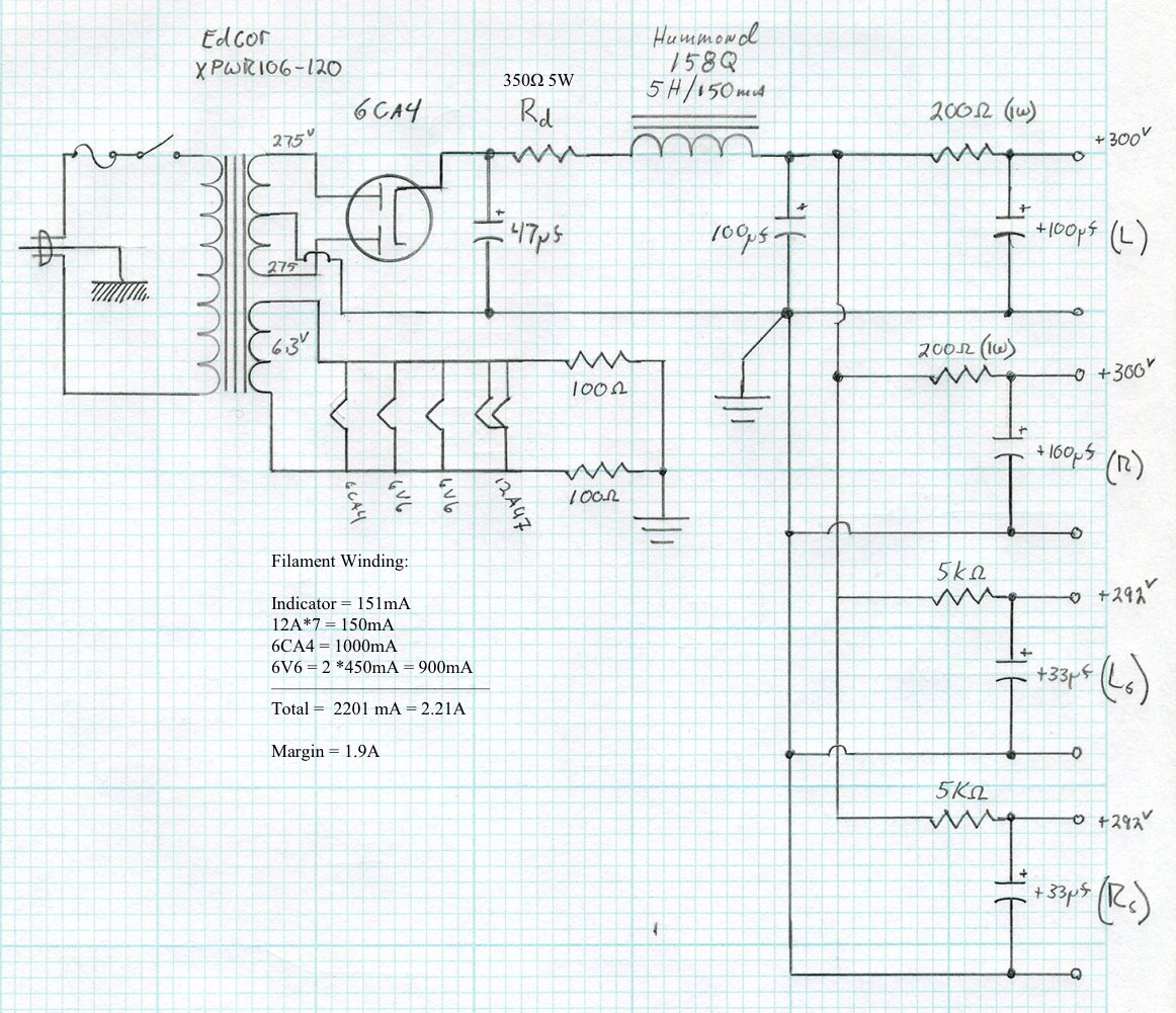
This power supply also has some nice features. As mentioned above, it only has a single filament winding which simplifies the power supply wiring. In addition, it uses only a single, relatively inexpensive, open frame filter choke. This helps contain the overall rice of the amplifier but, in combination with the additional R-C filter stages, still provides significant isolation guaranteeing a very deep and wide soundstage. Finally by using a power transformer with a substantial filament winding, there is enough margin to use the 6W6 power tubes with ease.
The Build
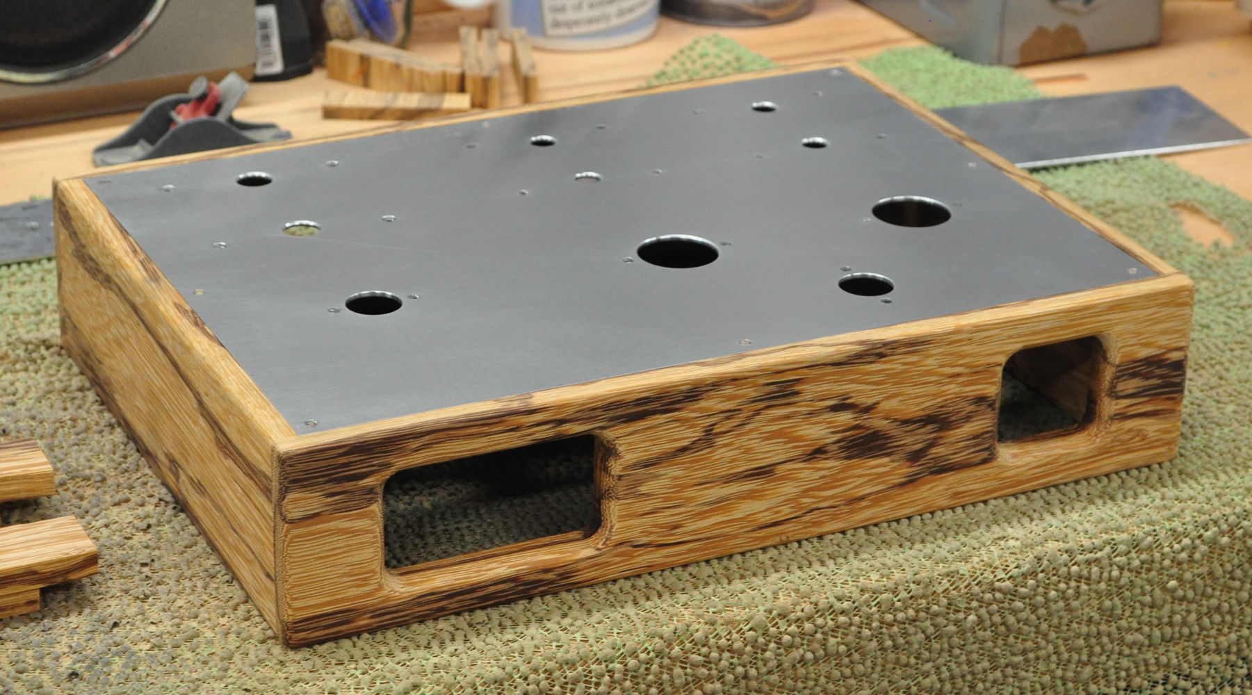
I wanted a layout for this design that a first time builder would not find too complicated. I also didn’t want it too large so that a standard commercial amp chassis could be used if desired. Here is the layout for the top upon which I settled.
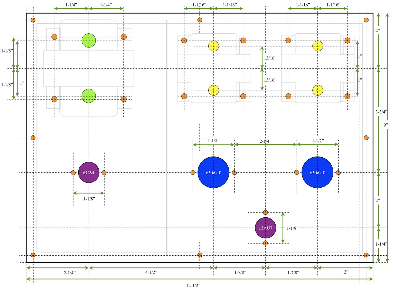
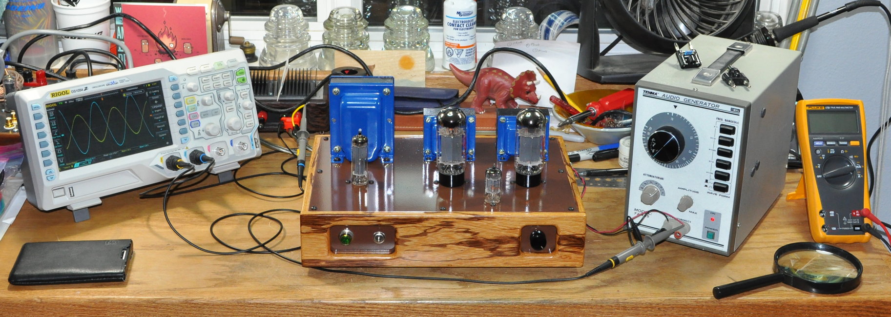
This layout puts the power supply on the left and the audio portion on the right. This also provides ample separation between the two sections. With simple modifications this layout can go on commercial chassis as small as 8”x12” without too much trouble. Here is a picture of the raw chassis and top plate sitting on the workbench in my wood shop.
 I started assembly with the top plate, and installed the transformers, tubes sockets, terminal strips, ground buss and miscellaneous hardware. Here is a photo of the underside of the top plate with this initial work accomplished.
![]()
This picture illustrates an important concept I use during layout process. I use terminal strips with lugs on 3/8” centers. When I perform the initial layout I pay special attention to alignment and separation between items mounted to the top plate. This allows me to use existing mounting screws to mount the terminal strips. underneath without needing additional screws protruding on the top plate. This simple bit of planning really helps keep the top plates looking clean and uncluttered in the final builds.
At this point I perform as much wiring of the top plate outside of the chassis as possible. This ensures that I have very good access to every connection from pretty much any direction. This allows me to see everything and not have to contort my hands to get a soldering iron, solder, or pliers in position.
This approach also has another benefit. It allows me to perform some basic chassis wiring without having to work around the top plate. Since my chassis are essentially a wood “ring frame” that goes around the amp. Not having the top or bottom plate installed makes it a much simpler matter to run some of the other wiring. Here is a picture of the chassis after I’ve done some preliminary routing and wiring for the power transformer primary circuit and for the audio inputs and volume control.
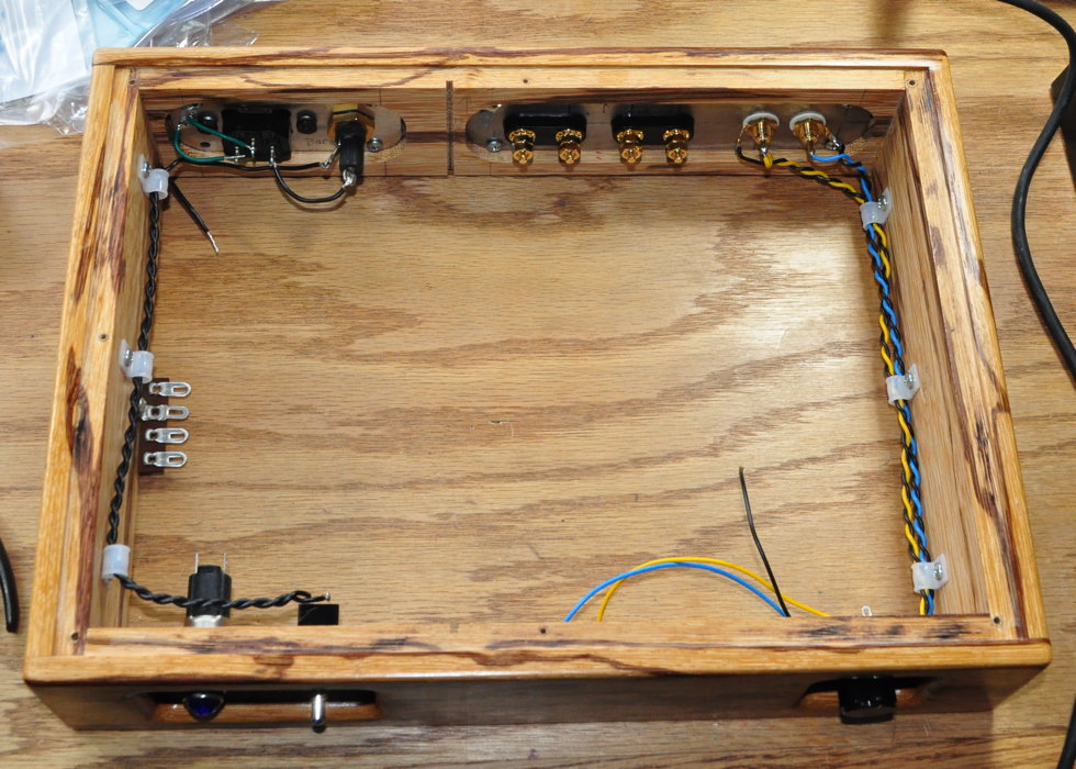
This wiring and routing was much easier to accomplish with access from both sides of the chassis. By performing the major wiring in two steps this way, it means that I have very few connections I have to make once the top plate is installed. Here is a picture of the inside of the chassis with the top plate installed and the wiring all completed except for the B+ dropping resistor.
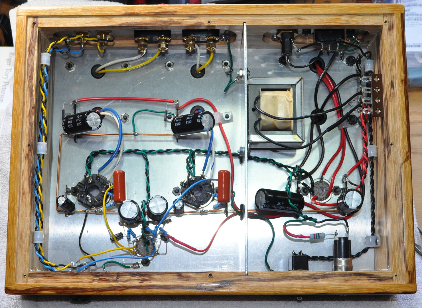
I will also note that I even installed the main power choke on the separator plate prior to sliding it into the slots cut in the chassis. I really think this is not too complicated a chassis layout. Even though it is point-to-point wired, it is not too crowded and it is relative easy to see all the connections.
Testing
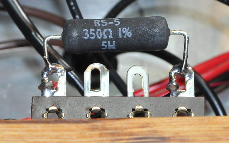
The initial testing was just to determine the appropriate B+ dropping resistor. After doing some spot checking I settled on a 350Ω resistor. Total current load for the amp with 6V6s is about 95mA. At 350Ω this equates to a power dissipation of about 3.16W. I settled on a nice 5W wire wound resistor shown below.
 With this installed both 6V6s were showing 16V cathode bias values and plate voltages of 272v. The initial testing with the chose NOS GE power tubes showed significantly higher distortion at one watt than I expected. So I switched them out for a pair of National Union 6V6GTs which showed much better behavior. Here are the summary numbers with the 12AU7 driver and the NU 6V6GTs.
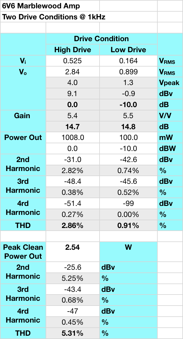
This is good behavior for an amplifier of this type. Distortion is very low at low output levels, at 1W the distortion is well controlled and virtually all 2nd harmonic, and even at 2.5W, it is still just at the ≈5% level and still virtually all 2nd harmonic. I am very satisfied with these results. As a point of interest, I define “Peak Clean Power Out” by visually watching the output waveform and increasing the levels until I just begin to see a little compression on the peaks of the sine wave. This is not the maximum output power of the amp but is a good reference for when the distortion characteristic changes from predominately 2nd harmonic to a more “transistor like” distortion characteristic. Here is the waveform plot for the 6V6s at “max clean power”.
 And here is the accompanying FFT of the output waveform.

So on paper the amp looks good. But what about how it sounds?
Impressions
The amp sounds fabulous. I initially spent about two hours trying all different types of music to see if I could find some sonic problems. I could not. It handled classical, opera, choral, jazz, rock, hip-hop, country, even Gregorian chant with no problems whatsoever. As is typical with these output transformers, the amp is very fast with excellent transient response.
In addition, the amp is dead silent with absolutely no int of hum or hiss. And when the music starts playing the sound stage is both deep and wide. Individual instruments and vocals seem to simply rise up out of the dark abyss.
This amp has truly excellent sound and performance. I would highly recommend this build for anyone looking to build a nice simple amp with great sound.
And About That Versatility?
So as I mentioned above, this circuit is designed specifically for the 6V6 power tube and 12AU7 driver. However, by using the “Universal” preamp design as the basis for the driver, and by using the ≈390Ω cathode bias resistor on the power stage, it allows this amp to handle a large number of different driver/power tube combinations. This is an especially nice attribute for someone just starting out with tube amps and wanting the ability to “try out” some different tubes without switches or having to make modifications.
Just for reference, the acceptable driver tubes are: 12AU7, 12BH7, 12AV7, 12AY7, 12AT7, 12AZ7, and 12AX7. It should be noted that these tubes can produce wildly different gain values which will significantly change the sensitivity of the amplifier. When swapping driver tubes start with the volume setting very low and increase as necessary dependent on the drive level supplied to the amplifier. The acceptable power tubes are: 6V6, 7408, 6L6, 5881, 6F6, and 6W6. These all have slightly different levels of bias requiring different level of drive to reach full power. And each has a different sound quality when paired with any specific driver tube. This equates to 42 separate and distinct combinations of driver and power tubes you can use with this amp. Here is the amp under testing with a 12AU7 driver and a pair of JJ 6L6GC tubes.
 Although I did not test all 42 combinations, I did test a few different power tubes with a 12AU7 driver. Here is the summary distortion and peak clean power data for the 6W6, 6L6, and 6F6 power tubes.
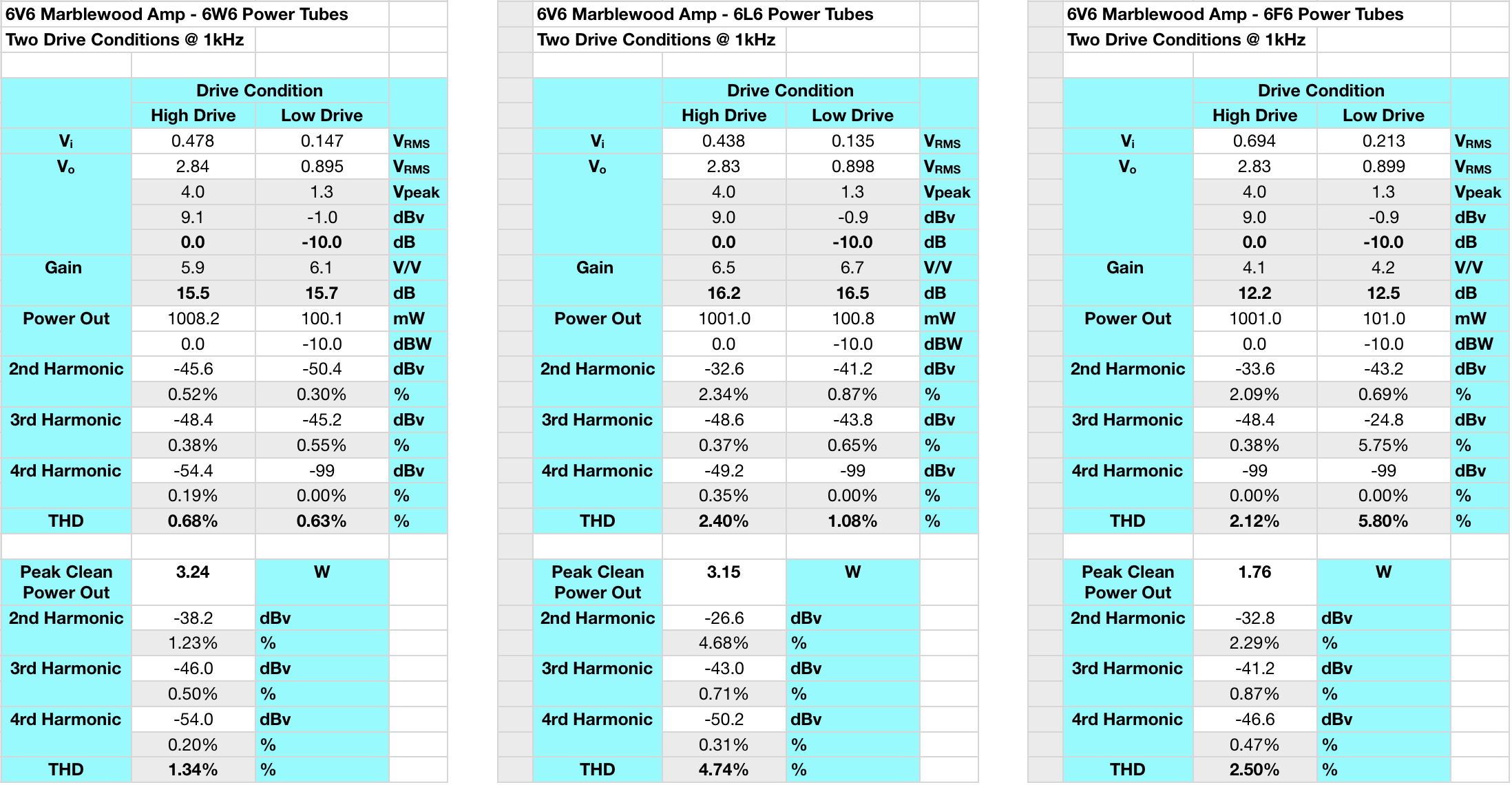
As can be seen from the data, it looks like the 6W6 is the best best for power and low distortion, the 6L6 is a good trade between the two, and the 6F6 is low power but also lower distortion than the 6V6 at moderate drive conditions.
Summary
 So there you have it. A relatively simple stereo amplifier with great sound and true tube rolling versatility. This project was a lot of fun. And it provides yet another example of how great results can come from simple designs.
So let me know what you think of the “6V6 Marblewood Universal” amplifier.
Ciao,nel preamplificatore color utilizzi 2 triodi per canale,mentre nel marblewood utilizzi solo 1 triodo per canale come preamplificatore.
> Hi, in the color preamplifier you use 2 triodes per
> channel, while in the marblewood you only use 1
> triode per channel as a preamplifier.
Yes that is correct. In each channel of the color preamp one triode is a gain stage. However, the second triode functions as a buffer to allow the unit to drive low input impedance amplifiers. The buffer stage does not provide any gain or tonal shaping to the signal. It is there solely for interface purposes.
Matt, if you were to optimize the voltage amplification stage for use with 12AU7 only, what changes would you make?
That word “optimize” is a dangerous one. The original design for the marblewood has the 12AU7 running at a pretty good operating point. It has ample headroom to drive any of the usable power tubes and it is mostly neutral. I’m not sure I would change anything.
There is one thing to consider however. In this post on power stage topology I discussed the different topologies and I noted that UL topologies have a tendency to sound the most neutral. And, in my opinion, I believe that the marblewood is a good example of this neutrality without adding too much color to the overall sound. Now, if one really wanted to add a little more color to the sound then you could pick a new operating point for the 12AU7 to provide it. If I were to do this, I would probably use the plate load and cathode bias I used in the 12AU7 Color Preamp. This would mean increasing the cathode bias resistors to 2.4kΩ and decreasing the plate loads to 50kΩ.
Just be aware, that once you make those changes it’s really not a “Marblewood” amplifier anymore. All the versatility built into the driver stage is gone. You can still roll all the different power tubes, just not necessarily the driver tube. Not that this is bad, it’s just different. And in the end, it’s your amp so you should make it sound exactly how you like it.
Thanks for the insight on that Matt.
I’ve decided on making the following changes to the amplifier.
1. Swap the 10W Edcor OTs for 15W to get some better low-end performance. My frequency response test shows -7dBr at 20 Hz. This is a little too much roll-off for me and I can definitely hear it compared to the 6AS7 and my 300B.
2. As I plan on using only a 12AU7 preamp tube, I’m going to adjust the operating point. I like your suggestion on using the Color Preamp value. I’ll study the data sheets and see what makes sense.
3. Change the first power supply capacitor (47 uF polarized) with a 33 uF Solen film capacitor. I used this Solen for my 300B and then swapped one in on the 6AS7 and to me it sounds slightly better.
4. I may change all audio path resistors from metal film to carbon film. Again, I’ve used carbon film for my last two builds and the sound is great. Probably doesn’t affect the sound very much, but I figure why not.
I’ll let you know how the mods turn out.
Matt,
Checking back in to let you know the results of my modifications. I should point out that it is no longer a Marblewood and more akin to your Lacewood V2. I’ve lost the versatility that the Marblewood offers, but I was never going to use anything other than 12AU7.
Each channel of the 12AU7 is now running at:
Vk = 8.1 V, Vpk = 145 V, Ik = 1.5 mA
Each 6V6 is running at:
Vk = 16.7 V, Vpk = 272 V, Ik = 42 mA
(your 6V6 optimization)
B+ for power and signal stages is 300 V.
Frequency Response:
Before (10W OPT): -7.5 dB @ 20 Hz, -0.65 dB @ 20k Hz
After (15W OPT): -3.3 dB @ 20 Hz, -0.7 dB @ 20k Hz
Modifications made:
1. 5.6k ohm instead of 1.2k ohm for 12AU7 Rk.
2. 0.1 uF instead of 0.47 uF for coupling capacitor.
3. 3.3k ohm instead of 5k ohm for B+ (s).
4. GXSE15-5k-8
The sound is fantastic. It’s like the Marblewood on steroids. A lot more presence in the lower end, yet still retaining fabulous clarity.
Hi Matt,
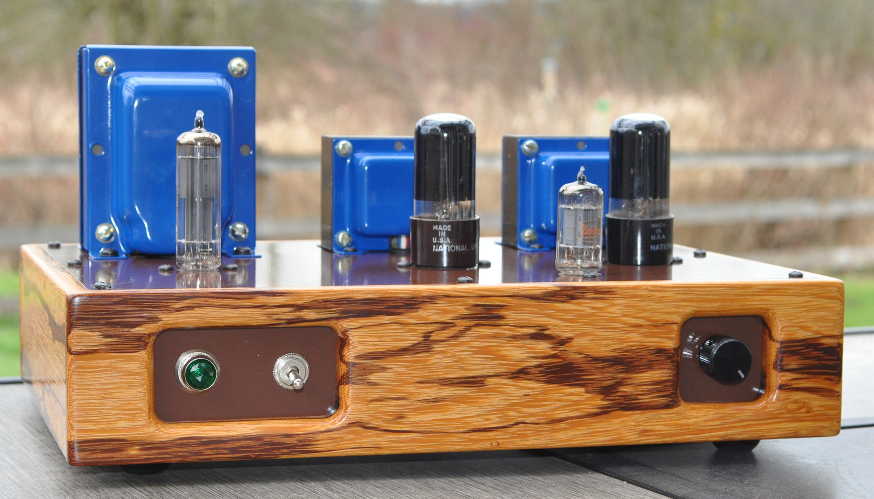
I’m about to start marking your 6V6 Marblewood Amp as an assessment project. I thank you for your posting this project on your website. The only comment I have is that it would be helpful, for me in particular with limited electronics knowledge, if you could include a photo of the rear of the amp or post one in your response?
Here is a picture of the finished amplifier from the back.
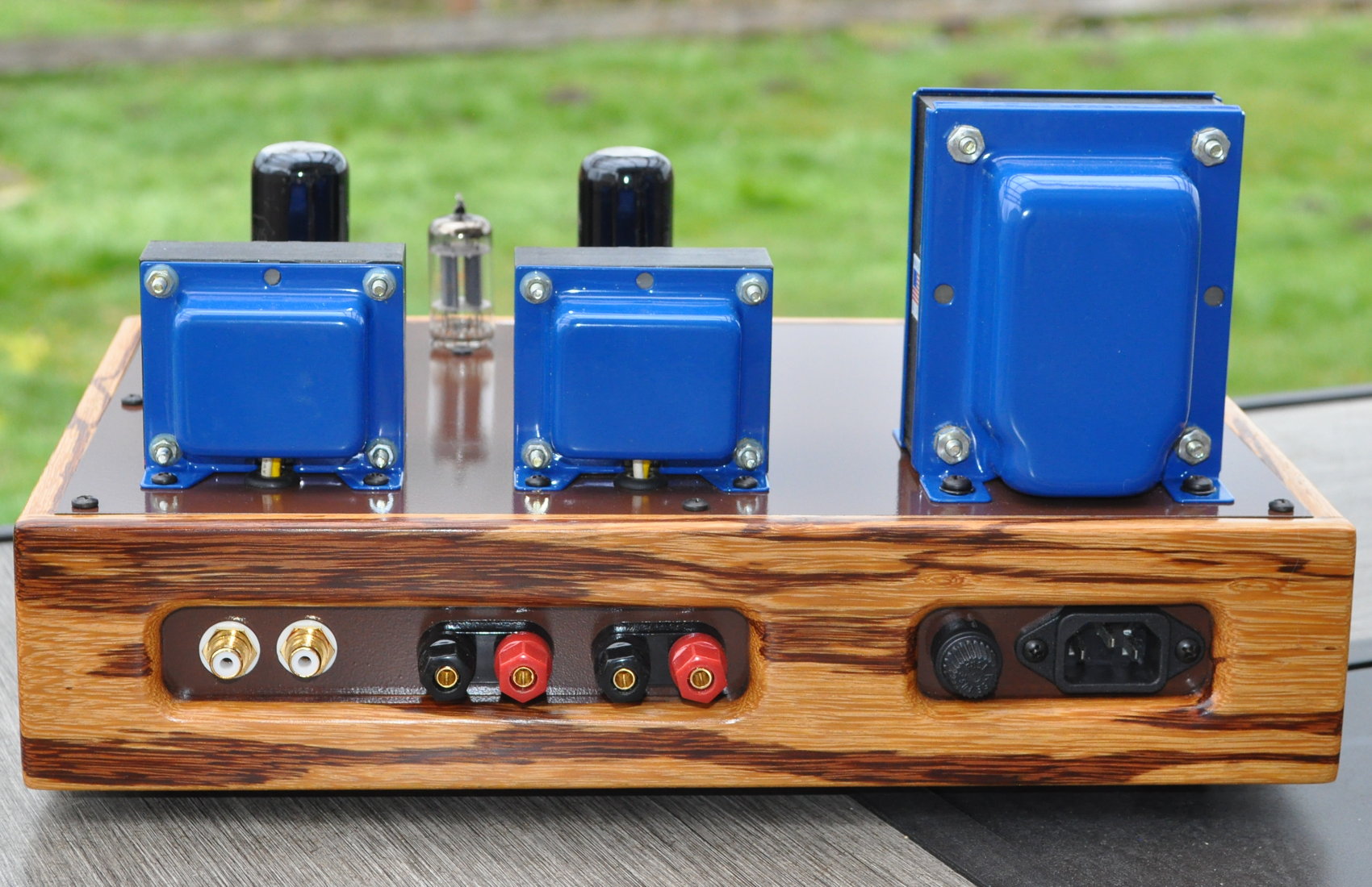
I hope this helps.
By the way… what’s “an assessment project”? I’m curious.
Ciao Matt.
A quando Marblewood v2.0 ?
Angelo
>> When is Marblewood v2.0?
It’s not even on my list. I am still very satisfied with the 6V6 Marblewood.
The Marblewood was designed as a “first amplifier” project for people who had never built an amplifier from scratch before. The power stage is optimized for the 6V6 but can handle a bunch of other tubes. The signal stage is based on the 4S preamp and can handle all the tubes that the 4S can use. The project is relatively inexpensive to build and produces a great result.
I can’t think of anything that I’d do differently.
Ciao Matt
Lo so,loso, lo ho realizzato,e,suona veramente bene.
Stasera lo ho provato con delle 6l6G Fivre con driver 12BH12 .
Per le 6l6 preferisco la 12BH7 che spingono di più .
Ho sostituito le resistenze di catodo delle finali e del driver con altre di potenza maggiore perché quelle scaldavano molto.
Una modifica che sto facendo è la possibilità di avere doppia alimentazione sia a valvola 5u4g e anche con diodi al silicio selezionando tramite commutatore.
Angelo
> I know, I made it, and it sounds really good.
> Tonight I tried it with 6l6G Fivre with 12BH12
> drivers. For the 6l6 I prefer the 12BH7 which
> push more. I replaced the cathode resistors of
> the finals and the driver with others of higher
> power because those were very hot. A modification
> I am making is the possibility of having double
> power supply both with 5u4g valve and also with
> silicon diodes by selecting via switch.
With the rectifier switch, be aware that the B+ with the silicon diodes will be higher than the 6CA4 rectifier. As much as 40v higher. The 6W6 and 6F6 should not be used in this configuration.
Ciao Matt.
Il trasformatore di alimentazione che sto usando è di 260+260v da 168w quindi con i diodi al silicio la tensione ottenuta è giusta com progetto.
Invece con la 5u4g la tensione ottenuta è di circa 10v meno.
Ho sostituito il primo condensatore d’alimentazione con un da 40 mf ad alta tensione in poliestere .
> The power transformer I am using is 260+260v 168w so
> with the silicon diodes the voltage obtained is correct
> according to the design. Instead, with the 5u4g the
> voltage obtained is about 10v less. I replaced the
> first power supply capacitor with a 40 mf high voltage
> polyester one.
Ciao Matt
Usando 260+260v con la 5u4g devo eliminare la resistenza da 350 ohm.
Ottengo circa 10v in meno.
> Using 260+260v with the 5u4g I have to
> eliminate the 350 ohm resistor. I get
> about 10v less.
I finally finished my Marblewood this evening. I started it late last year but had to put it on hold for several months. Have been listening to it for about 30 minutes now. First, I’m just so happy that it works. Second, the sound from it is very appealing to say the least. A few tracks by Ahmad Jamal have been simply sublime. I’m using Definitive D11 bookshelf speakers that are rated 90dB. The bass is clear and articulate and highs are crisp, really nice. A fellow listener described it as “slightly warm” and I would have to agree. Finally, I should note that the amp is dead silent even at full volume. The tubes are Mullard 6V6GT, Mullard 12AU7, and Sylvania 6CA4 (USA), all new.
Thanks Matt for making this information available and for all your support.
I’m glad you like the amp. I agree that, with the 6V6s, it is slightly warm. If you want more warmth try the 6F6s. And it you want more neutrality, try the 6L6s. The versatility of this design makes it one of my favorites.
Matt,
I’m close to wrapping up the build of this amp and I’m thinking about my next project. I’d like to build a preamp for a MM phonograph to feed the Marblewood design. Do you have a design that you would recommend for this application? There is a circuit in the RCA RC-30 manual I’m considering, just wanted to get your thoughts before plunging into the unknown.
Thanks.
I’ve built the circuit from the RC-30 manual and it’s okay, but nothing spectacular. And the buffer on the output really needs a fairly high load impedance to maintain the performance. If you really want to build one of your own (and you want tubes) I would highly recommend Bruce Hernan’s “Groovewatt” (March 2016 edition). It’s a much better preamp albeit a little more complex.
When building a high gain signal chain like an RIAA preamp please be aware that layout, lead dress, grounding, and shielding are VERY important. Start with a large enough chassis and then make it bigger. Go slow, plan your layout with an eye to interference and interactions. High gain chains can regenerate easily. And use tube shields. They will definitely improve the noise floor.
Thanks for the heads up. Given the noise requirements, it’s probably too advanced a build for me at this point in my journey. I think I’ll build a SET amp next, and then think about tackling a RIAA preamp.
Hi Matt
In the Marblewood amp power supply, separate final filter stages are used for the left and right channels. Could you explain the advantage of doing it this way?
This power supply topology promotes very good channel separation. Usually increasing the channel isolation by a significant margin. Amplifiers with good channel separation are often described as having a “wide” soundstage and good “imaging”. These are the amplifiers where you can pick out the physical placement of individual instruments. It is this type of imaging that made mono-blocks so popular.
Thanks for your prompt reply Matt. I have built a very similar amp to your Marblewood except that it has a common power supply for both channels. When I play a signal through only 1 channel there is no audible sound from the other speaker. So it seems channel separation is complete, without needing to separate the power supplies.
I have now measured the channel separation on my amp using 8.2 ohm resistors in place of the speakers. Signal (1KHz sine wave) was applied to the input of left channel only. Output voltages (rms) were: L channel 3.62V, R channel 31.2mV.
This is a voltage ratio of 116 which equates to greater than 40dB of channel separation. So if one channel is producing 10 watts, the bleed into the other channel is less than 0.001 watt.
I am deeply skeptical that increasing the channel separation further would have any effect on “imaging”and the superiority of monoblock amps in this respect is clearly another audio myth.
The issue of necessary channel separation is a tricky one. Most stereo music mastered prior to the 1980s did not have that high a channel separation simply because the channel separation of multi-channel tape and phono styluses seldom exceeded 30db to 40dB. And, of course, nothing recored live will have that high a channel separation.
However, the advent of digitally mastered music completely changed thoughts on channel separation. There is a lot of studio music mastered digitally with channel separations in excess of 70dB. I know that the 1992 digital remaster of “Dark Side of the Moon” has significantly increased channel separation over the original LP. (Although I’ve been told that the original quadrophonic masters are an experience.) The new remaster announced by Roger Waters will likely also have significant separation on at least some tracks. There is also a significant amount of new jazz mastered in the last 30 years or so with really significant channel separations (>60dB) specifically to help image individual musicians in the sound stage. And you can tell the difference on some tracks.
Also, power supply channel isolation is a frequency dependent phenomenon. You should be really checking it with pulsed frequency waveforms in the 100Hz to 500Hz range. It also matters if there are single channel transients as they require more power supply separation to isolate channels. And, of course, any time you’re using headphones, channel separation can really make a huge difference with digitally mastered music.
As I said, this is a tricky subject. Because it depends not only on the amplifier, but the way the music is mastered, the storage and playback mechanism, the speaker sensitivities, the ambient listening level, and the background noise in the listening area, it can be difficult to judge at times. I build in more channel separation in my amps because with some music I can really tell the difference. But I would never say that 40dB of channel separation is a bad number.
There is a helpful discussion on this topic at:
https://www.audiosciencereview.com/forum/index.php?threads/channel-separation.7452/
I didn’t find anything in the referenced link helpful. Mostly just unsubstantiated opinion. YMMV
Hi Matt,
Grounding question for you.
Is your ground bus (the copper wiring running through the amp and power supply) connected to the earth of the 3-prong power socket or is it left floating?
I had my top plate powder coated (on both sides) and I’m trying to determine the best grounding strategy. I was thinking about connecting all metal (tube sockets, etc) to the ground bus. What are your thoughts?
Thanks!
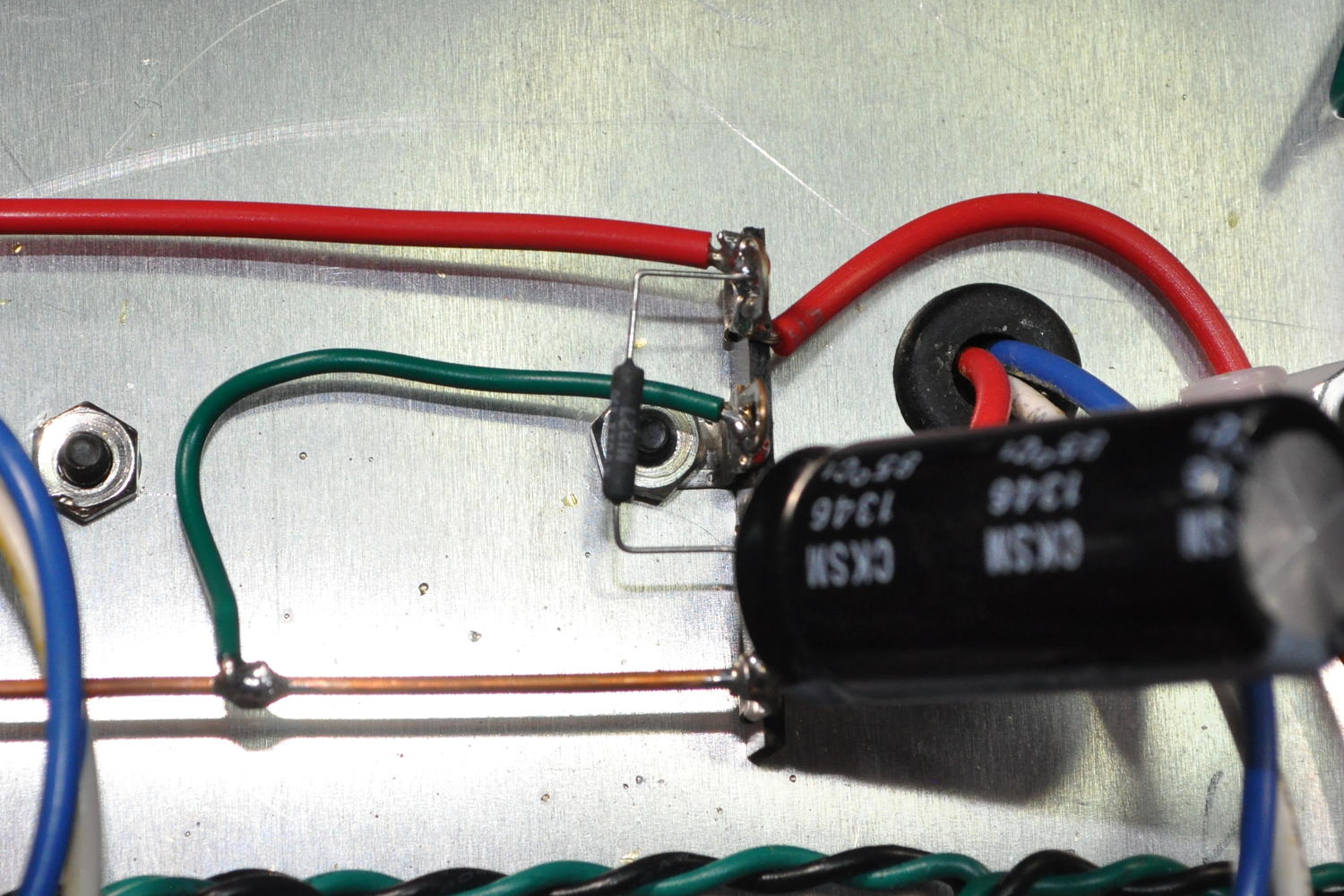
The signal ground (i.e. the bare copper bus) is connecter to the chassis ground (i.e the “earth” lead in the IEC connector) at only one point. This helps prevent ground loops in the signal chain. It’s the green wire in the photo below.
A complete discussion of my grounding philosophy can be found here: Matt’s Grounding Philosophy
Thanks Matt. Appreciate that quick and precise answer.
Hi Matt,
this AMP 6V6 is Tripole connection method or Standard method or UL method?
THANK u!
This amplifier power stage is UL connected.
Hi again Matt,
I’m working on a BOM for this amp. Was wondering if I could link you to it and get your opinion on the component selection and completeness of the parts list.
Thanks,
Alex
Here is the BOM that I developed.
6V6 Marblewood BOM (generic)
Let me know if this helps.
Very helpful. Much appreciated.
In my first amp build, I made the 6V6 bias adjustable by placing a 500 ohm resistor in series with a 1K potentiometer (between cathode and ground). This gave a 500 to 1.5k sweep to bias the tube between 9W and 14W of dissipation.
Do you see this being helpful for the Marblewood, given the fact that it’s compatible with so many different tubes?
In general I avoid things like adjustable bias in my single ended amps. In a P-P power stage I’ll almost always include a bias balance potentiometer, but not an overall bias adjustment. I like to get the bias point where I want it in the design and then fix it. If I swap in other tubes, it’s with the understanding that I accept the resultant bias point wherever it falls. If I include an adjustment then I end up fiddling with it instead of listening to amp.
The Marblewood specifically, was designed as a beginner amp with good sound and as simple and straight forward a design as possible. Yes you can use different tubes (mine runs almost exclusively with JJ 6L6s lately) but fiddling with bias really isn’t going to have that great an impact on performance. And it is possible that in changing operating points you could over draw the power supply or seriously degrade the transition characteristics during momentary overdrive conditions.
So in general, I don’t recommend adjustable bias for end product amplifiers.
Matt,
A couple quick questions on plate dissipation on the output tubes. Being as this amp design is really for the 6V6 which has a max plate dissipation of 12 watts.
The 6W6 is about 10 watts and some in the 6L6 family can be up to 30watts. Were you concerned about running the 6W6 a little hot and 6L6 a little cool when swapping power tubes?
Also are you designing in a safety margin to keep the plate dissipation below the max rating of what ever tube is being used. Any insight would be greatly appreciated.
First let me say that the design point really is for the 6V6 from the 6V6 SE-UL optimization study. So the performance of the 6L6 and the 6W6 are really fallout from that design. This is, first and foremost, a 6V6 design.
As for the performance with those other tubes that’s a different matter.
First, I have no concerns whatsoever about the 6L6 family. Yes this design runs them far below their potential but they operate rather well at the resultant operating point. In fact, my Marblewood spends most of it’s time with a pair of JJ 6L6S power tubes these days.
The 6W6s are indeed running hot in this design. How hot is a matter of speculation. The original ratings for the 6W6GT (from the 1950s) gave a plate dissipation maximum of 10W and a screen dissipation maximum of 1.25W. However, then Tung-Sol published data in 1962 which showed ratings, when used in a class-A1 amplifier, with a plate dissipation maximum of 12W and a screen dissipation maximum of 1.35W. I have a couple of pairs of Sylvania branded tubes which appear to be structurally identical to a couple of pairs of GE branded tubes I have. All these tubes are from the 1960s and have ribbed plates. I also have a pair of earlier RCAs with smooth plates. The ribbed plates typically handle more power dissipation than the smooth plates.
The combined dissipation I measured (plate plus screen) was ≈13W during testing with the Sylvania 6W6GTs. When I first discovered this I was concerned. However after running the amp with these tubes for many continuous hours and experiencing no red plating or problems of any sort, I decided that it was ok.
The 6W6 was originally designed for use as a vertical deflection amplifier in large televisions. This can be an abusive environment for any tube. My supposition is that there is enough margin in the tube design that the additional dissipation in the Marblewood is not an issue. At least for the 6W6GTs with ribbed plates. I might run a test sometime with the smooth plate RCAs in a dark room. Just to see if I get any indication of overheated plates.
To throw tube variable in the mix. I have some 6DG6-GT tubes. They were listed (on AES) as 6DG6/6W6,. When I look at tube data sheets, the plate dissipation is listed at 10 watts, but with a maximum plate voltage of 200. I guess one would gamble and just try it in the amp?
The 6DG6 is actually a 6.3v filament version of the 50L6. I’m not sure what kind of response it would produce in the Marblewood design. You might want to check the operating point first.
Thanks Matt. I have some RCS 12W6’s that would be better candidates
Coming up with 12. volt heater power would be easy enough. But my current focus is on your 6L6-SE. I’m ready to drill the chassis
Hi matt, im gattering all the required parts for this amp, but in my country the ez81 rectifier tube is pricey for my budget, instead the 5y3 is cheaper, can i use the 5y3 in place of ez81 with a hammond 272DX wich provide a couple volts more on the HT side and a 5v filament supply?
Best regards
This would be an acceptable substitution. You could also try the 5U4, 5U4GB, and GZ-34 rectifiers in the amp to adjust the B+ voltage.
Matt,
Thank you! I just finished my first stereo amp (marblewood). The sound is amazing! I am very happy with the result. I strongly recommend this project. Some pictures:
https://photos.app.goo.gl/nKfv6zMEh5YtqPuc9
I’m glad you like the amp. It’s a beautiful build. I love the finish on the iron. Did it come like that or was it something you did?
I bought the aluminum sheet and a cutting and bending service. Then I spent several hours sanding and polishing until I got this finish. The entire process I posted on my Instagram (@gugarn). It would be a pleasure to receive your visit.
Hello,
Thank you for this amazing project. I decided to build this amp, however I bought two audio transformers without center tap (my mistake). Is it possible run this amp in Pentode Mode? What do you suggest me? Thank you.
You can run this amp in pentode mode with about 250v on the screens. It will be bias more toward cutoff than is typical so it should sound warner than most pentode amps. But I really cant quantify what the actual performance differences may be.
Wow. Thank you so much for this experiment and for sharing this build. I am not green per se, but I am not totally immersed, either. I trouble shoot and fix amps, and I build mostly lower type voltage preamps, but this is a real treat. Thanks again.
Great work here and THANK YOU for making your work public. I’ve recently caught the hifi tube bug and have spent many Saturday mornings cruising the web for a simple design that I could do some experimenting with. I was torn between basing it on 6V6 or 6L6 tubes and couldn’t decide on a driver. I was thrilled that your design would permit me the latitude to experiment with the options I had in mind…and many more. So now it’s time to get building! As I get started, a couple questions came to mind…
1. It’s been a bit since you designed this… Any lessons learned or tweaks that you’d recommend?
2. As I’m somewhat new to hifi audio amps (my experience in in vintage console radios) I’m very curious to experience the UL vs triode differences. Would it be practical to add the option to this amp? Is it as simple as adding a SPDT switch to select the UL tap or plate voltage for the screen? Any resistance advised? Or is this just a bad idea?
3. Any recommendations for a suitable speaker setup to pairwith this amp? I’ve had my eye on the Klipsch RP-600Ms (96 dB). I would think high efficiency would be important with this amp…but am I going overboard?
Glad you like the site. As for your questions, I’ll take them in order.
1) My only suggestion is the one I give everybody. Build a bigger chassis than you think it needs to be. This 12-1/2″ by 9″ top plate is about the smallest you should build this amp. It seems that I am always looking for more area and/or volume while I’m in the assembly phase. Bigger chassis also tend to minimize internal interactions yielding a quieter amp.
2) Personally I don’t recommend a switch mode topology. I know that people do this but the optimum operating points are so different for the two modes that the difference you hear is really due to one topology being run at a seriously suboptimal operating point. I recommend building the UL topology and later, if you want a triode amp, build a SET for comparison. The 6CY7 V2 is a nice option for a first SET.
3) Speakers are a difficult question. The really important requirement for speakers is you want ones that are “tight”. This means a low mass, relatively stiff cone but one that still has good bass response. Personally I would start with something at a little lower price point than the RP-600Ms. Not because there is anything inherently wrong with those speakers, but because these amps are a different breed from the solid state amps and global feedback tube amps. That’s why so many folks recommend the Fostex full range drivers for these amps (like the FE166NV). Zero feedback, vacuum tube amps have a higher output impedance and need well match speaker to really perform. Although I have found that some of the older mid sized book shelf speakers perform well. Just so long as the efficiency is relatively good (e.g like 89dB or better).
I hope I’ve answered your questions. Good luck with your build and let me know how it goes. If you have any more questions, just send me an email.
Thanks so much for the thorough response! Your thoughts on topology vs operating point make sense and I think I’ll heed that advice. That’ll get me started on ordering parts and I’ll use the meantime to further research speakers. Thanks again.
Thanks for sharing another great design. Dig the clearly laid-out decoupled filter stages. I’m not seeing any feedback. Is that correct? I had been under the impression that tetrode-based amps such as this one required some NFB for correct operation. Guess not.
I would agree with you if the tube were running in pentode mode (i.e. screen grid at constant bias). But it is not. In this amplifier topology the power tube is run in “UL” or “Ultra-Linear” mode. Here the screen grid is run off a tap on the primary of the output transformer. Running a Beam Power Tube in this way generates mostly 2nd harmonic distortion and not the odd order harmonics.
Feedback suppresses the first few harmonics but promotes the higher order harmonics. Only Beam Power Tubes run in pentode mode may need feedback to tame the distortion spectra.
I see. My current 6L6 project amp has the UL taps but I have it switchable btw UL and Triode-Strapped. Didn’t realize NFB had a different effect on those 2 modes. Maybe I should have a NFB defeating switch in there.
https://imgur.com/a/Kx98zV7
I would play with the bias point as well. See my 6L6 UL optimization article.
RCA hum reduction circuit. Matt, I was looking a an old RCA Receiving Tube manual. In the circuits section they have several HiFi amplifier circuits with various versions of a hum balance adjustment to minimize hum by placing some DC bias on top of the ac filament voltage.
What do you think about this?
This is really two separate issues. One is “hum balance” and one is “filament DC offset”.
With respect to hum balance, I believe this is largely a holdover from the age of DHT (Directly Heated Triodes). When using DHTs with AC filament voltages, it is important to “balance out” the AC waveform across the heater such that the midpoint is at the same potential as the cathode virtual ground. If it’s off, there is a small differential AC current induced on the cathode which mixes with the signal and introduces hum. For most unipotential cathodes, this is not required. I have never run into a case of unipotential cathodes requiring a hum balance pot in an audio amplifier.
The second issue, filament DC offset, is more complicated. Usually, in an audio amplifier designed for line level inputs it is not necessary to provide a DC offset to the filaments. On my amps I keep the filaments at zero DC offset with two 100Ω resistors, one connected to each side of the filament and signal ground. This is not to say that it doesn’t necessarily make a measurable difference, just that it’s not usually required.
The exception is in audio circuits with large amplification factors and designed for small input voltages, such as RIAA preamplifiers or microphone preamplifiers, it can make a difference in overall noise and hum. As an example; the specification for the 12AX7A for equivalent noise and hum with 6.3VAC heaters is 1.8µV RMS across ∂f=[25Hz..10kHz]. This is -115dBV. However, where input voltages are a few mV, this may put the equivalent noise and hum in the -75dB to -80dB range which may not be acceptable in some applications. However, I generally find this to be a special case.
I have the parts for the Lacewood V2.0. I assume I could use the power supply circuit from the Lacewood for a Marblewood build by changing the 20k resistors to 5k to get the 292V outputs. Would any of the capacitors across the 300V or 292V outputs require any changes?
You should be good to go using the Lacewood V2 power supply with the Marblewood amplifier. The capacitor values are fine. It is a slightly cleaner power supply than the Marblewood’s however the differences will likely be inaudible. Just make sure when selecting Rd to set the power stage B+ under load to as close to 300V as possible (e.g within about +/-10v or so). This is the optimization point for the Marblewood topology.
Thanks, Matt!
Hello again Matt !
Just a quick message to say A BIG THANK YOU !! for sharing your knowledge.
The Marblewood Amp was finished on Easter Sunday … (albeit without wood), it sounds really nice, I love the wide sound-stage & the clear channel separation, maybe due to the smart PS ? Overall it is a very convincing amp, and my only worry so far is the heating of the mains transformer. (Hmmm ?) I warmly recommend it as a first-time project.
The 6W6 has a plate rated at 1.2, and the KT66 is rated 1.3 Have you tried a KT66 in your amp?
I assume that you’re referring to heater current and not plate current. And yes, you are correct that the Marblewood supply could support the KT66 heater current.
However, I have not tried the KT66 in the amp because I haven’t assessed the KT66 operation at the Marblewood bias level. My initial look indicates that the cathode current would be in the neighborhood of 73mA. This is too high for the power supply in the Marblewood. I would recommend that you not try to use the KT66 in the marblewood without significant power supply modification.
Matt,
Thanks for the quick reply. Everything you said makes sense, especially the cathode voltage and current being a little low. I was just curious, and since this thread had a post two weeks ago I thought I would ask.
Sorry for the vague numbers in the question. You are correct about the heater current. There are 4 amps. The rectifier gets 1, and .3 goes to the dual triode. If there is no light, then about 2.6 amps are left. 2.4 amps for a pair of 6W6s is safe, but I was curious how much cushion was there.
I have not built the amp yet, because Edcor is a busy right now. Once the transformers comes in, then I will get started. I have a piece of Walnut for the chassis and some stainless steel for the top. I am also working on drawing the terminal strip connections.
I am looking forward to building the amp,
Dan
Is it ok if i replace resistor
390r with 2w rating
5.1k with 4.7k
No. Using such a large biasing resistor will result in power stage bias well beyond cutoff. This results in hard class-B operation which is unsuitable for audio.
Thanks for the reply. I ask because that is what available on me and i dont know nothing about tube amplifier.
I will buy the right resistor and start building this amp.
I am sory. Perhaps it is a bit unclear. What meant was
-R bias from 390 3 watt change to 390 2watt rating. Is it safe?
– r grid 5k change to 4.7k. Is it ok? Or is it better to change to 5.1k.
The power dissipation on the 392Ω bias resistor is just about 1W. A 2W resistor should work fine. Changing the grid stopper resistor to 4.7kΩ is also acceptable. I apologize for misunderstanding your first post.
Hello Mr Renaud,
First let me congratulate you on your willingness to share all that knowledge of yours & your energy to help newbies (like me) get into the joys of Tubes. Your site is awesome, really.
Your explanations are always very clear & even for a beginner, they are interestingly educational. Your designs are so simple, & your choice of tubes is refreshingly unusual.
I find your fascination for the various wood types amazing, when your readers are focusing ( & probably sweating a bit like me) on the intricacies of circuits, you indulge in finding good looking woods for your enclosures… That is real luxury !
As a beginner I read your recommendations & before I start with the Marblewood amp, I have a few questions :
I am currently living in Thailand, some questions are related to the challenge of procuring the parts out here so far away.
– My mains is 50Hz : Is there any significant impact on the values of the power filter components ?
– I checked how to order the Edcor power & output transformers from the US but shipping only will cost me about twice the value of the products so I will source those here in Asia. I could find an appropriate power transformer (made to order), but the output transformer is more of a challenge. I could get a 4,2kohm 10W output trans. Could that be acceptable ? and would it mean adjusting the values of components around the power tube ? Sorry for my lack of knowledge …
– Would there be a benefit to a delayed start of the tubes to prolong their lives ? such as the ones found on commercial amps.
– Is there a need for fine BIAS adjustment if the two 6V6 tubes are not “matched”.
I wish you & your loved ones all the joy that this festive season can bring, a merry Christmas & a better 2021 than 2020 !!
Thanks. I’m glad you’re enjoying the website.
The power supply filter does not need to change for 50Hz mains. Just make sure you get a power transformer wired for your local power standard.
Sourcing parts is always something that can take some work depending on where you’re located. You can use a 4.2kΩ primary output transformer. But it does need to have a 40% UL tap for the screen grid.
You do not need to do a delayed power change. Actually, using the vacuum tube rectifier means that the B+ will rise slowly as the other tubes heat up. This means the lowest stress on the tubes and the longest tube life. Delayed power setups can actually cause more stress on tubes if they are not implemented correctly.
Don’t worry about matched tubes and bias adjustment. Since the tubes are not running in push-pull but independently, no bias adjustment is required.
Merry Christmas to you too. Please let me know if you have any other questions.
Hello again,
Thanks a lot for your fast & clear answers !
I will source the parts & get to work !
Until then, Have a great new year, and hopefully a better 2021 than 2020 :-).
Hi Matt … I love your designs. I wanted to ask you if in this circuit I can use the 6l6g of 19w dissipation or I can only use the 6l6gc of 30w.
The table below is the voltages I measured when using 6L6 output tubes.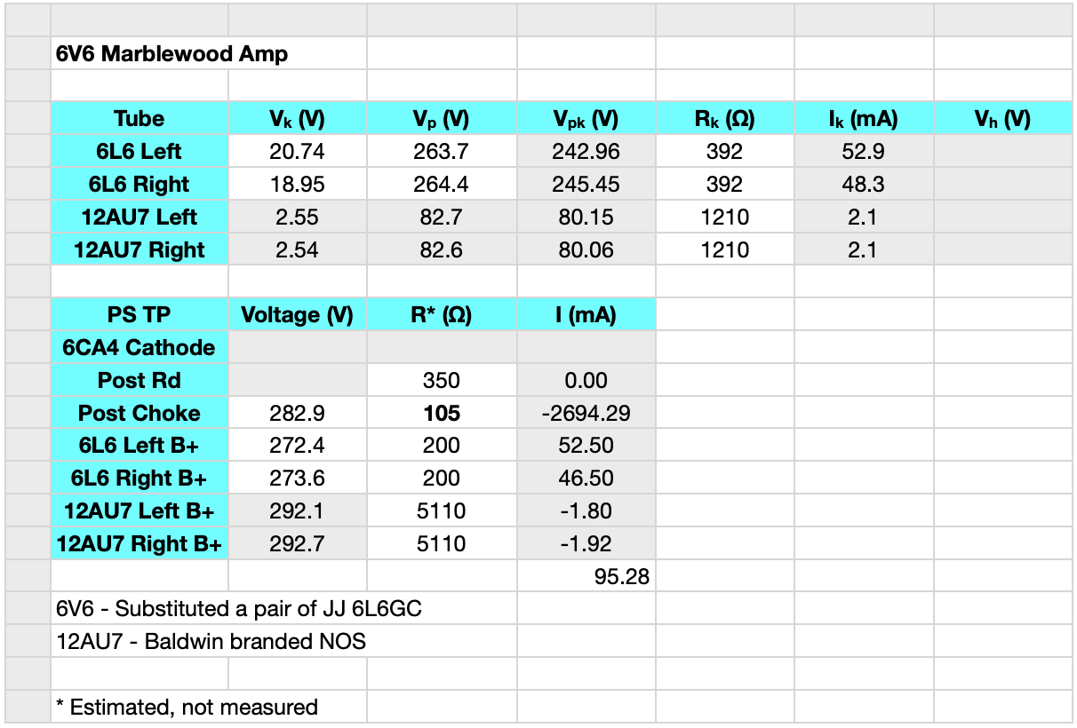
As you can see, the plate dissipations are well under 13W. As such you can easily use the lower power dissipation 6L6 and 6L6G tubes in the Marblewood amp.
Can an 8K be adapted to this design, or does that throw its qualities out the window? I have a small budget and 8K are what I have on hand. Thanks for posting this!
The Marblewood power stage is really optimized for the 5KΩ power stage load. With an 8KΩ load I am guessing that distortion overall will be lower. However, the bias points will probably not be nearly as good as with the 5kΩ load. Personally I would not recommend it unless you did some bias point optimization at the 8kΩ load.
Thank you. I’ll locate some 5K transformers.
Can I use the 7C5 Loctal tube instead of the 6V6?
Yes. Make sure you wire the different pinout.
Just be aware that although the 7C5 is advertised as a direct replacement for the 6V6, it is not an exact duplicate. It will work but the sound and performance may be a little different.
Hi Matt!
Having built the 4S preamp already and intending to use it with the Marblewood Amp would it be a no-no to drop the 100k input potentiometer? Maybe switching it for a resistor is a better idea?
Personally I recommend you retain the input volume control on the Marblewood. The marblewood is a relatively sensitive amp and you’ll probably need the input volume control to control overdrive conditions.
Matt,
I just finished this build and did some testing. First off I can’t believe this thing worked straight away. Not because of design but because usually everything I build takes some fiddling around with to get to sound good. This design is great and sounds incredible. We don’t have the cleanest power and this amp is dead silent until music starts. I’m currently running it into some mid efficient Dayton full ranges that I built for now and I’m stunned how loud and clean it sounds. Sound stage is wide and I hear things in songs that I’m familiar with that I never knew were there. I’m thinking of keeping this in the office and building the 6336 and putting that in the living room with some fostex high efficient full ranges. For now I’m going to be very happy listening to this amp.
The Marblewood is one of my favorites. I’m really glad you like the design. Try one of the little SETs if you get the chance. I really like the 6CY7 amp for jazz and instrumental.
Hi Matt,
Is there a BOM with the capacitor voltage values available?
I don’t have a complete BOM but the capacitor voltages are as indicated below:
• All power supply capacitors are 450VDC electrolytic
• The power stage bypass capacitors (i.e on the 6V6s) are 50VDC
• The driver stage bypass capacitors are 25VDC
• The interstage coupling capacitor is 450VDC
I hope this helps.
Perfect, thanks.
Just finished my version, not marblewood but black walnut. Have done a bunch of tube swapping and settled on new JJ 6V6S and JJ 12AX7. Love it! It’s supposed to be for my sister but I’m going to have a hard time giving it up. I’ve compared it side-by-side with a Bruce Heran “Poddwatt” and they really have different character. The poddwatt sounds positively boring by comparison, though it has a little more punch at higher volumes.
Thanks for posting such a great design! Wish I could post a photo here.
Would you recommend this for a turntable/CD player amp?
Yes. It has a great sound for vinyl. However, depending on the turntable cartridge you may need a preamplifier.
If you are using a turntable with a magnetic cartridge (MC or MM) you will need an RIAA preamp. These days I am recommending the kit from Boosehound Labs. Here are some links:
https://boozhoundlabs.com/collections/all/products/bhl-audio-jfet-phono-preamplifier-kit-2sk170-riaa
http://diyaudioprojects.com/Solid/JFET-Phono-Preamplifier-Kit/
I recommend you read up on this solution and decide if it meets your needs.
As for CD players, I use my Marblewood for that all the time. It sounds great.
FYI It looks like boozehounds is closed with no plans to reopen.
Love your site. Thank you for the hard work.
Best,
Drew
Yes, I was saddened to see that Boozehound labs had shut their doors. The DIY community has lost a great resource.
Hi Matt,
I am trying to figure out the voltage rating required for the capacitors that join the 6V6 cathode to ground. I think they are bypass capacitors?
If I knew the maximum expected voltage at the cathode, then that should guide the required rating for the capacitor.
I found a data sheet for the 6V6 tube which lists the maximum plate current as 47 mA (at 250V for the plate). The current through the plate should be the same as the current through the cathode. Then using that current, and the resistor value, I come up with a voltage of 18.4V at the plate (47 mA across a 392 Ohm resistor).
I am even close on this? Or way out in left field?
Thank you – Gustave
You are very close. The cathode carries both the plate current and the screen current. If you look at the Optimization of the 6V6 SE-UL page, you’ll see that at 300V B+ the plate current is ≈45mA and the screen current is ≈5.7mA. So 50.7mA*392Ω is ≈19.9v. As such, the bypass capacitors should be rated by a comfortable margin above this. I don’t know what I used but is was probably somewhere above 35V. I like lots of margin.
OK, that’s great. Is there any benefit whatsoever from going with larger than required voltage ratings on caps?
Longevity? Performance? Acoustic quality?
Not really. There are some that swear that special capacitors (e.g. special silver foil blessed by mystics and hand rolled on the thighs of Japanese virgins under the light of the full moon) make a huge difference, but I’ve never been able to hear any difference.
8^)
Hello Matt,
Me again…
The coupling capacitor between the driver tube and the power tubes is shown as 5.0k Ohm. The closest I’ve been able to find is 5.1k Ohm. Am I not looking in the right place. How significant would this difference be?
Thank you – Gustave
The coupling resistor is there to limit frequencies above 20kHz. With the 5kΩ resistor the amp is only down less than 1dB at 30kHz and 2dB down at 40kHz. Substituting a 5.1kΩ will have no effect on the sound.
Got it. Thank you.
Hello Matt.
Another question from a newbie, hope you don’t mind.
I have been studying your circuit diagrams for this amplifier. And trying to put together a real world wiring layout. But I am having trouble meshing the two schematics.
On the power supply schematic, far right side, are the B+ voltages for the driver and power stage plates (300V and 292V respectively). But the schematic also shows a matching ground path for each B+ path? I cannot figure out where that is meant to go. Unless maybe it is shown on the schematic for completeness?
The amplifier schematic shows the tube cathodes connected to ground via a resistor and bypass capacitor. Is the ground the same as the one I speak of above (the mates to the B+ voltage supplies).
I hope this question makes sense. It would be easier for me to explain if I could post pictures here.
Thank you – Gustave
After looking at my schematics I can understand your confusion. The additional ground paths on the power supply schematic are really just shown for completeness, as you said. Those lines could just as easily stopped at the negative side of the 4 final filter capacitors. Note that the ground reference is actually connected to the negative side of the 100µf capacitor following the 5H filter choke.
There are actually only two grounds. One is the signal ground indicated by the triangular ground symbols and the other is the chassis ground indicated by the rectangular ground symbol. If you look at the third picture under “The Build” you’ll notice a heavy gauge copper wire suspended on terminal strips. This is the signal ground for the amplifier. All the triangular ground connections shown in the schematics tie to this single heavy copper wire. If you look to the far right you’ll see the power transformer center tap already soldered to the end of the signal buss.
When complete, I tie the signal ground to the chassis ground at a single point. This helps prevent ground loops and hum. You can see this jumper in the picture below. This is actually located at the end of the signal ground buss near the connection to the output transformer.
Does this make the grounding scheme clearer?
Yes, that makes sense. I like your grounding philosophy. Thank you.
Gustave
Hello,
I am going to try to build on of these amps.
I have a question regarding the output transformer(s).
The circuit diagram lists a GSXE10-8-5K
On the Edcor website I see either a GSXE10-8-8K or a GSXE10-5K with options for output impedance (to match speakers I am thinking).
My gut tells me the GSXE10-8-5K from the schematic has 5K input impedance with 8 Ohm output impedance. In other words the GSXE10-5K with the 8 Ohm option. I just wanted to double check here before ordering.
Thank you – Gustave
Yes, you are correct. Edcor has slightly changed their numbering scheme since this was posted, but the product is still the same. The proper product number is now the GXSE10-5K with the 8Ω option chosen when ordering.
Thank you Matt. I actually have 4 Ohm speakers so will select that option. I am looking forward to this build!
Matt,
I’m assuming that all resistors are .5 watt metal film unless specified in most of your builds including this one. But you know what happens when you assume. Another question is how would using carbon comp change the sound, and are you using metal film because of tighter tolerances?
Yes. All resistors are 1/2 W, 1% metal film. There are only three exceptions to this. The power stage cathode bias resistors are 3W, 1% wire wound resistors, the B+ dropping resistor is a 5W, 1% wire-wound, and the indicator light series resistor is a 25Ω, 3W metal film.
I use metal film resistors due to their excellent noise characteristics. They are very quiet and that’s the way I like my amps; quiet. Now there is one reason to maybe insert some carbon in the signal chain. This is perhaps if you like that very slight background sound of the old tube amps. In this case, substituting the driver stage load resistor with a carbon composition resistor will add a hint of the old school carbon sound without affecting the noise figure of the amp too much. There are some people that swear by this for warm tone. I’ve tried it and, although I can notice the difference, I still prefer the metal film resistors in this application.
Hope this helps.
Great design
If I use a 5K single-ended output transformer and there is no 40% super linearity, what changes need to be made to the circuit diagram?
Thank you
If you have no screen tap, you need to make a decision.You have three options; run the output tubes in pentode mode, run the tubes in triode mode, or get new transformers. The first two options require you to pick a bias point, then calculate the cathode current to set the self bias resistor.
This is really a serious departure for this amp. If you email me we can discuss further.
Hello Matt,I’ve just finished building an amp based on your Marblewood design. I thought it would be good to use a uk made transformer set but the mains tx didn’t have a centre tap on the HT. This was got round by using a hybrid rectifier,negative half silicon,positive half an EZ80. It works fine but the voltages are a bit higher than yours. I had to wire the 6v6s as triodes too. No matter it sounds lovely. I’d send a picture but I’m not sure how to do that being an internet newbie! Thanks for the inspiration.
Dave; Glad you like the amp. Just email me a pic if you get the chance.
Hi Matt, I just finished an amp based on your marblewood design. However I used an old 1948 Crosley radio (I like the look of the vintage wood radios). The chassis, tube sockets, power transformer, 5y3 & 6v6 tube were all still usable. Obviously using these parts there was no guarantee on how well the amp would perform but it sounds great. The one hiccup was on your schematic it looks like a 39.2 Ohm power tube bypass resistor. Once I relized my mistake I substituted a 392 and all voltages were up to spec. Thank you for your excellent design.
I’m glad you like the amp. Do you have a picture of your build? Would be great to see it.
Hey, I’m a first time tube amp builder and for my first build I decided to to build your marble wood amp.
I just had a few questions regarding connecting the power supply to the two channel. Are the grounds shown on the power supply chassis grounds and the grounds shown on the signal go to the B- voltage?
The key here is really the shape of the ground symbol. If it’s triangular, like in the center of the the PS schematic, that’s a ‘signal’ ground. If it’s rectangular, like on the left side of the power transformer on the power supply schematic, that’s a chassis ground.
If you look at the 6th figure down which shows the top plate before wiring, you’ll see the heavy copper ground buss suspended on terminal strips. This is the “signal” ground in my build and it is isolated from the chassis ground which is all the exposed metal on the amp (except signal jacks). All ‘signal’ ground connections get tied to the signal buss, and all the exposed metal gets tied to the ‘chassis’ which it tied to the ground wire of the mains connector.
When the whole amp is wired I connect the ‘signal’ ground to the ‘chassis’ ground at one point. If you look at the picture of the wired amp, you’ll see bent green wire connected to the signal ground buss between the output transformers. This is a single point tie between the signal grounds and the chassis grounds. This eliminates ground loops.
Does this help explain the ground structure?
Matt – forgive my ignorance, but you have discussed SE UL output for the Lacewood topology. In the above comments you mention a differentiation between UL and SE as being different. Can you help clarify if configured for an SE output is UL an aspect of impedance matching with the OPT or a separate tap on the OPT? What configuration is the Maplewood, Lacewood and why.
Thanks,
Thomas
PS – I gathered the parts to create the V2 Lacewood. It sure looks like I could use the PS section as is (float CT of heater) and build out the Maplewood amp section and adjust plate voltages. Are there any risks in doing this?
Thomas; I’ll answer your PS first. If you look closely you’ll see that the Lacewood V2 and the Marblewood actually have the same power stage design. The differences between these two amps are the driver stage and the power supply rectifier and details. Using the Lacewood V2 power supply for the Marblewood is fine. It also has the added advantage (because of the extra 6.3v current availability)
of allowing you to also run KT-88s in the Marblewood which you can’t do with the published power supply.NO, Don’t ever put a KT88 in the Lacewood or Marblewood designs. Bad things happen!The answer to your first question is more complicated. First, All the amps on my site are currently “Single Ended” or SE designs. This simply means that the power stage uses one tube per channel to generate power. This is all that is meant by “SE” in this context. Second, the Lacewood and the Marblewood both have Single Ended Ultra Linear (or SE UL) power stage topologies.
There are three basic topologies commonly used for pentode power stages; Pentode, “Ultra Linear”, and Triode. The primary difference between the three is how the pentode screen grid is driven. In Pentode configurations, the screen grid is held at a constant voltage so the screen voltage does not change as the plate voltage waveform oscillates. In Triode mode, the screen grid is tied directly to the plate so that the screen voltage is identical to the plate voltage and precisely tracks the plate voltage waveform. This makes the pentode behave very similarly to a traditional triode but severely limits the peak power available.
In Ultra Linear mode, the screen grid is tied to a tap on the primary of the output transformer that is between the fixed B+ voltage and the plate voltage. Typical tapping points are 23% and 40%. This mode helps to cancel some of the undesirable odd order harmonic distortion of the pentode mode and yet produces significantly higher peak output power than the triode mode. It also has a “sound” that is distinct from either the pentode mode or the triode mode. This is my preferred topology for running power pentodes and beam power tubes.
I know this isn’t a very complete description but I hope it answers your question.
Hello,
I think I’m going to build this as my first tube amp. I just read a book by Robert megantz, and have a better understanding but I’m still partially confused lol! I’m sure it’s calculated, but how do I know to use a 1w resistor, 5w etc.. same for capacitors. There are many sizes from small to large.
Is there a chance there is a parts list to this schematic?
Thank you
Resistor wattages are based on the resistor value and the current through the resistor. Power dissipated Pd=(I^2)*R. As an example, the cathode bias resistor in the power stage is labeled 3W on the schematic. The current through the cathode resistor is approximately 50mA (from the 6V6 Optimization Study). So, 0.050A squared is 0.0025. This multiplied by the cathode resistance (392Ω) is actually a little under 1W. But I wanted to be able to use a bunch of other power tubes in this design. The rating of that resistor was increased to 3W so it could handle all the other power tubes.
Capacitor values are based on the desired operating points of the circuit.
i Just Wanted to Share my Creation That was inspired by the 4s Universal Preamp
and the 6V6 Lacewood Power Amp Section Combined with a 5u4G Rectifier
The Look is one of a Kind
https://www.instructables.com/id/Playstation-3-Stereo-Vacuum-Tube-Amp/
Pretty Unique. I like it!
Matt,
I am building the Lacewood V2 and was planning on making the 4S preamp integral to the amplifier. Your implementation of the preamp stage here moves the volume to the back. Would I be any better served using the original 4S design or what you’ve done here, in my case?
In the Lacewood V2, the 6V6s are only biased at 16.8 volts. As such, you really don’t need much gain to drive the amp to full power. In this case, with a 6SN7 driver gain of a little over 16 v/v, you only need about 1.04v peak (0.73v RMS) to drive the amp to full power. I would recommend against an integral preamp as you would likely have serious overdrive issues. If you really must, I would leave the volume control before the 6SN7 and ADD a second volume control on the input to the 4S preamp. You will likely need both to avoid overdrive issues.
If you’re really looking for an integral 4S preamp I highly recommend the Marblewood amp. This uses a 4S as a driver and allows serious tube rolling in both the driver and the power stage. This might be a better solution for you. Just a thought.
Hi Matt,
A pretty amp, and so versatile.
I’d like to build one, but also like the idea of including a Baxandall Tone Stack after reading the 2015 thread. Did you ever build the preamp using 2 treble, 2 bass and 2 volume controls?
Matt, I like the idea of building this amp with a Baxandall Tone Stack. I’ve been reading your thread from 2015 where you said your build would have two treble, two bass and two volume controls. Did you ever build it? What do you consider the pros and cons of a tone stack to be?
That project is still on my to-do list. Personally I like a tone stack because it allows me to tailor the sound to fit the room and my tastes. I know there are some people that simply won’t tolerate a tone stack. This is mostly because so many tone controls color some band regardless of control settings. A properly designed Baxandall tone stack is not like that. These, when properly implemented, are truly “neutral” when the bass and treble controls are set at the midpoint.
Quick subjective question:
You have both SET and UL pentode amps, from the listener’s standpoint, what are the audible differences in sound between the two types?
From a tech standpoint, I know that triode = even harmonic distortion, pentode = odd harmonic distortion
UL pentode = ??
When it comes right down to it, I would classify them like this:
The UL output stages tend to be very “neutral”. I think if a person is looking for the sound of a piece which is closest to the actual recording then the UL pentode power stage is the best bet. I only say this after listening to a fair amount of classical music live and the exact same performances recorded.
SET stages are anything BUT neutral. They are warm, rich, and full and they provide this unique color to everything they reproduce. This is one of the reasons they are so popular in spite of their typically low power output. They just sound fabulous with so many types of music.
Pentode stages are the most “transistor” like. (I know that’s not much of a description but it’s accurate.) They tend to sprinkle in the complete set of harmonics and inter-mods, so that while they can sound quite good, I find them to be the most cold sound reproduction.
Thanks,
I’m very familiar with the transistor sound.
The last tubes I have heard were in a pair of Dynaco monoblocks (push-pull 6550’s UL with a fair amount of NFB) with an all tube preamp back in the 70’s.
But, I have a nice tube type FM stereo radio out in the garage (6BQ5 SEP’s) that I think I might restore over the summer – to ease back into the tube sound.