
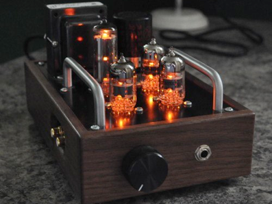
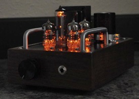
When completed, my new little headphone amp looked great. Four tubes glowing on the top, it was just waiting for the first music. So, with much anticipation, I hooked up a portable CD player, plugged in my headphones, and listened to the results of my labors.
All I could hear was hum! Lots of hum. Hum at zero volume, hum at max volume. Hum with music input, hum without music input. Hum, hum hum. LOUD hum. The music had to really loud to be even heard over the hum!
I was devastated. I had failed miserably. Not that there was anything wrong with the circuit design. Chu’s circuit is excellent and my power supply was very clean. It was my execution that was flawed. I tried shields. I tried alternate grounding schemes. I tried additional filtering. I tried everything that 20 years of designing, building, analyzing, and testing of the world’s most advanced aircraft avionics had taught me. All to no avail. Regardless of what I tried, the hum persisted.
As it turned out, I was still being haunted by the cult of the transistor. The 20 years of being an avionics designer had taught me too well. Small wasn’t just better, it was required. Everything had to be packed in tight. Everything had to be as small as possible. And with modern circuits, this is possible. When voltages are a few volts max and currents measured in microamps, it’s not hard to make things small. A little shield here, a simple ground point there, and everything works out pretty well. However, when voltages are measured in hundreds of volts and currents are tens of milliamps, things are not so simple. Fields interact, voltages are induced in everything, and layout is more then just important, it’s critical.
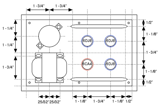
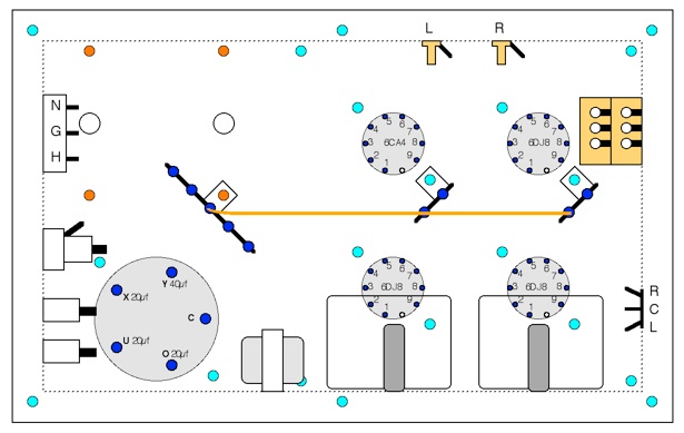
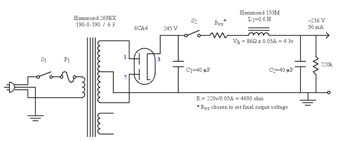
So, I went back and looked at chassis layouts of old radios, transmitters, and amps. I reread the section out of the RCA Receiving Tube Manual (RC-30 pg. 90) on the layout of high fidelity systems. And I looked carefully and critically at my amplifier. I had placed the rectifier tube right next to both the input gain stages and one of the output White followers (within an inch). This not only invited interaction between the tubes above the mounting plate, but it brought high voltage AC currents into very close proximity with input signal voltages below the mounting plate. I calculated the induced voltages in the wires of the gain stage components due to the power supply line currents. The results were not surprising.
I was inducing voltages of about 0.25v into my gain stage inputs simply by turning on the amp. There was simply no way this amp design was ever going to work properly. I had to start over. So I did. And the second time around, the results were everything for which I could have hoped. Look at “The Recovery” to see how I did the second time around.
However, I am determined that this amp will as yet get to see proper operation. The chassis design is simply too elegant to let it go quietly to the scrap heap. I have an idea for replacing the power supply with a solid state design. A new top plate, some better shielding and layout, and it may yet work. But first, I needed to recover from my initial failure.
I just want to say that I tell this tale of woe not because I want to trick or discourage anyone. I tell it so that others may learn from my mistakes. Because, in the end, life is about people and relationships. And if we can’t help each other out and learn something from each other, what’s the point of it all.
The output stage kind of reminds me of the typical OTL transistor output stage. Makes me wonder if it could be scaled up to drive a speaker at about a watt or so. Kind of a neat experimental project.
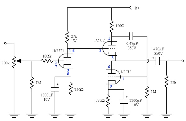
The 120-ohm resistor in the plate of the cathode follower is too low. It is necessary to insert at least 1kOhm to lower the output resistance.
This is Chu Moy’s reworking of Morgan Jones’ EarMax clone design. The output stage is a White Follower not a simple cathode follower. Raising the upper plate load will result in overload of the follower stage. Chu’s design is correct.
not commun cathode : cathode follower instead.
The signal stage in this design is a common cathode gain stage. The output stage is a White Follower.
Thanks for the RCA-30 p90 reference.
Thank you, this is indeed educational! Some time in the near future I will start to build my first tube amp as well and I have no electro technical experience or background at all. There is a lot to read about this, but most is technical and above my head. Your story does the job of teaching me something very well!
this is true SRPP buffer.