
Something A Little Different
When I posted The 6AS7 Purpleheart” SET amplifier page, I could not have anticipated the interest in the companion unit to this amplifier. So great has been the interest in this little unit that I decided to provide this signal meter component it’s own project page.
This is my first foray into using these ubiquitous little Vu meters. In the past I had always hesitated because of the meters’ unique driving requirements. The issue really lies in the standard for Vu meters in general. Mechanical meters have to be time averaging and this is usually accomplished with a very specific spring/mass balance. To properly drive this balance takes a little power. As such, these meters have an input impedance of approximately 7500Ω. They also assume a certain amount of drive capacity on the signal line.
Obviously this is rather low impedance to be directly connected vacuum tube circuits so in tube amplifiers the units generally require buffers. This usually means a combination of low gain buffer amplifiers and voltage pads for calibration, and, if staying with vacuum tubes, generally another dual triode. In the past, this increased complexity had always prevented me from including them in an amplifier project. However, it finally occurred to me that as a standalone unit, the build would be much more manageable.
Now for the awkward confession… this unit contains no vacuum tubes. When I looked at the requirements for a power transformer, HV rectifier, tube mounting, and other requirements, I had almost abandoned the idea yet again. Then, while searching the internet for ideas, I stumbled across a low voltage solid-state driver board and set of meters for a relative pittance; $25.99 USD. For that price I ordered one just to see what it was like.
The Electrical Design
As one might imagine, when utilizing a professionally built and integrated board, the electrical design process is really somewhat simple. When the kit arrived it contained no documentation of any kind. However, the board itself was clearly labeled and not too complicated. I quickly determined that the input impedance of the board was a nice 50kΩ on each channel. While lower than that normally used in tube circuits, this is not really too much of an issue when shunted across the amplifier input volume control. It simply means a dB or two more coupling loss, but nothing too drastic. So here is my very simple schematic.
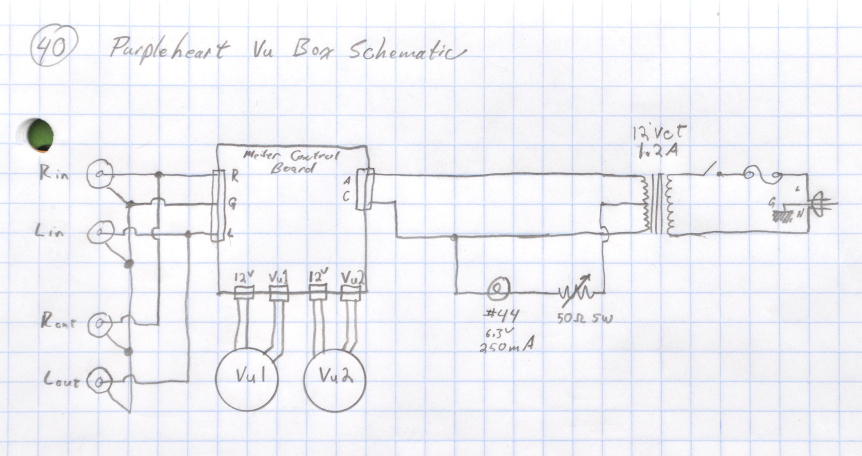
This unit is configured as a simple pass through with the inputs and output wired together. This wiring ensures that the downstream amplifier will function the same whether this unit is powered on or not. The unit is powered by a simple 12.6VCT, 1.2A filament transformer. The particular one I used has been bouncing around my parts box for over 40 years. I used my usual scheme for the variable intensity power indicator and connected it to one half of the transformer secondary. With the addition of a fuse and switch the design is complete.
The Build
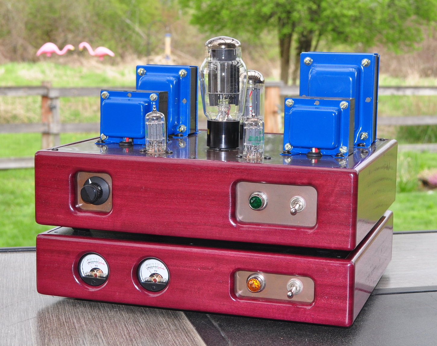
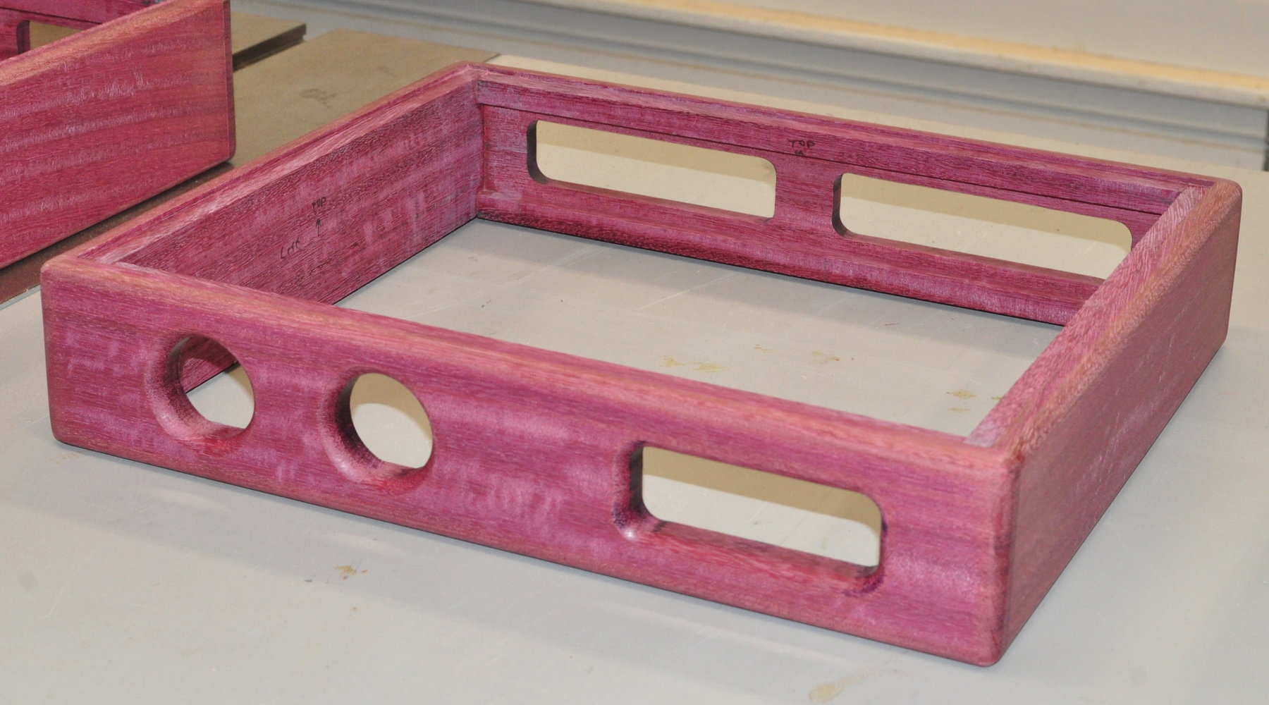
Since I wanted this unit as a companion to the 6AS7 Purpleheart SET, it was important that the units match. When cutting the chassis pieces for the SET amplifier I had a significant portion of the purpleheart plank left over. As such, I fashioned a chassis for this unit at the same time, out of the same piece of wood. Here’s the chassis after glue up before final sanding. That’s the side of the SET chassis to the left.
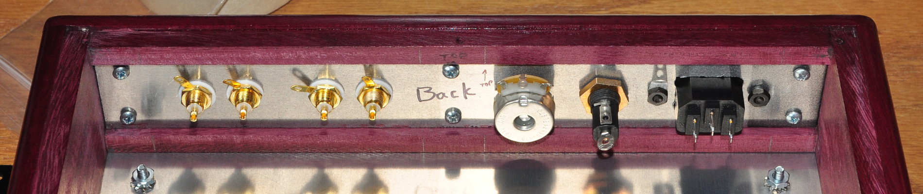
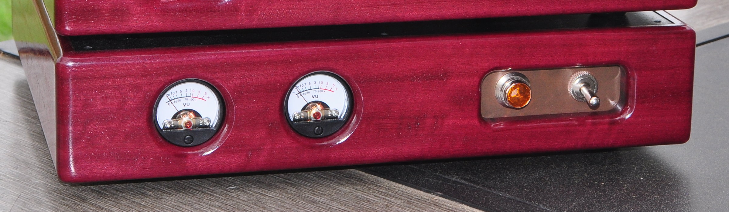
The front has the same tarnished copper plate as used in the SET to hold the power switch and pilot lamp. The back panel of the unit is painted aluminum. I finished the chassis with the same finish I used on the 6AS7 Purpleheart SET. Needless to say, the match is perfect. Here are the internal views of the front and back plates before I installed the meters and started wiring.
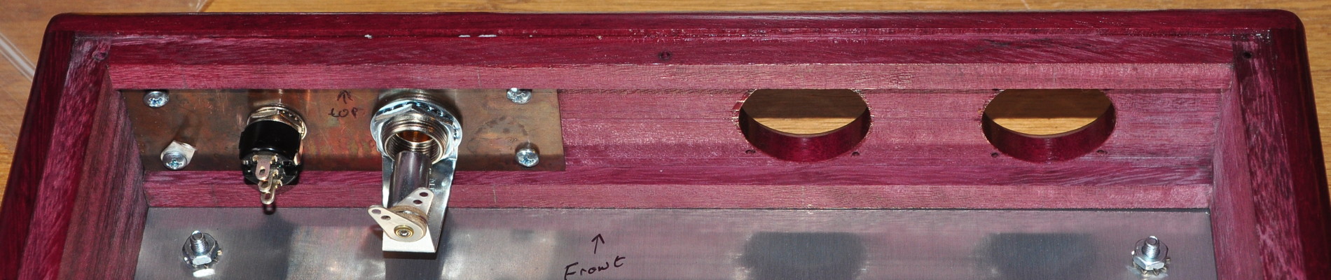
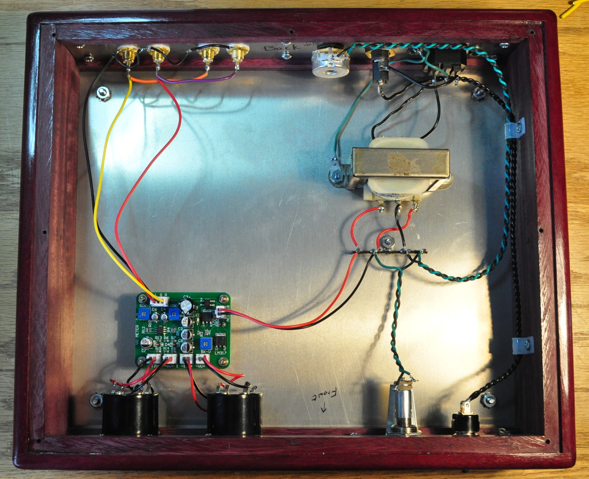
As I said, this was not a complicated build. I mounted the board on four M3 brass standoffs and the transformer with a couple of #6 machine screws. Heres how the chassis looks with all the wiring completed.
The most complicated portion was wiring in the control board. The wires supplied were rather fine, 26AWG, which required careful handling. A good quality clamping wire stripper (like this one) really helped.
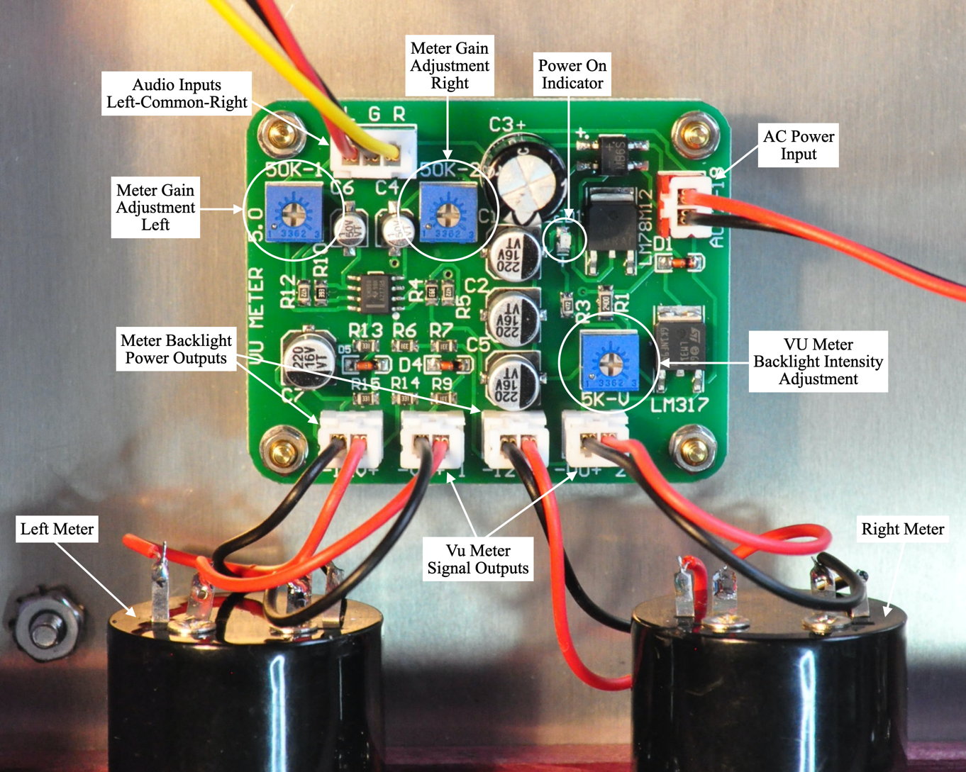
The board I received was different than the one pictured on the web. It looks like I received a “version 5.0” of the control board. This board allows for calibrating the meters to a known signal. It also allows the brightness of the backlights to be adjusted. The circuit board itself was of good quality, parts were properly aligned, and the flow solder job looked clean and professional. The board also has a small surface mounted LED as a power indicator. Here’s a close up of the installation with the various features labeled.
There were only two small complications to hooking up the board. The first was determining which of the connections on the meters were for signal and which were for backlight power. That was cleared up with an internet search and some common sense. The other was the confused labeling on the board. On this board the inputs are labeled “L G R” which I took to ostensibly mean “Left Ground Right”. However, the Vu meter outputs are labeled VU1 and VU2. I had to run a check with a signal attached to confirm “VU1” was the left meter and “VU2” was the right. Once completed everything worked as expected.
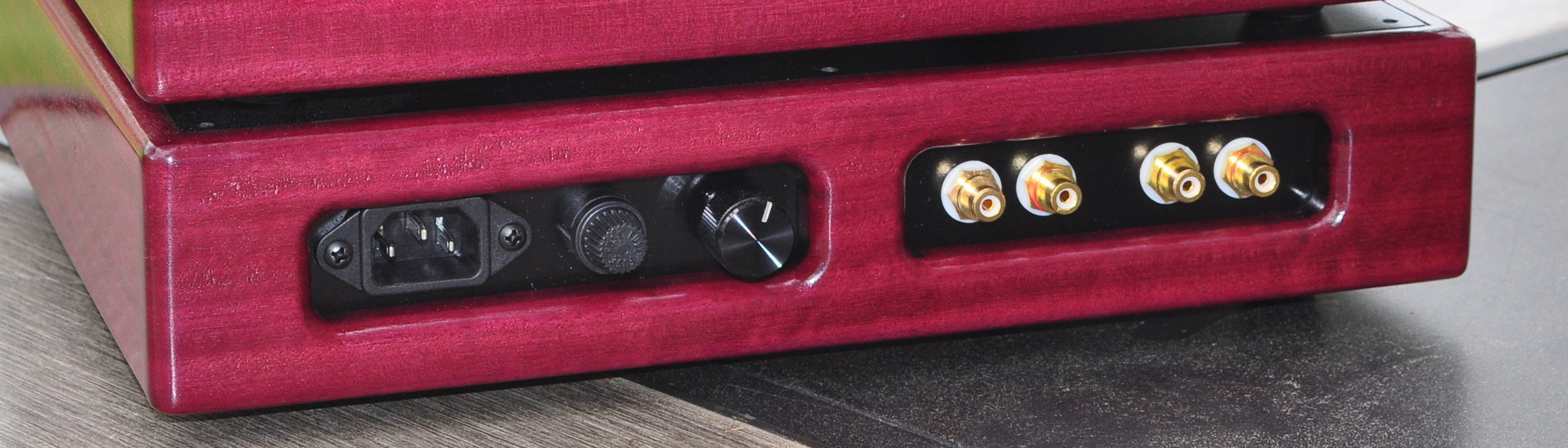
Here is the rear view showing the AC power panel (with indicator lamp intensity control) and the audio connections. The audio connections are color coded left and right and either set can be used for input or output.
Calibration and Test
First and foremost, this is a unit for metering audio signals. I wanted to make sure, more than just showing needles bounce, that these meters would relatively accurately reflect the signal amplitude of what was feeding the amplifier. That means that the meters need to be calibrated.
There is much confusion over “dBv”, “dBu”, and “VU”. The label “dBv” means exactly what most would think; decibel voltage. For dBv, 1.0v-rms equals 0.0dBv. This is a simple measure of a signal voltage. For “dBu”, it is also a decibel scale, but the reference is lower. For dBu, 0.775v-rms equals 0.0dBu. This means that dBu is always higher than dBv by 2.22dB. These are simply decibel voltage measurement standards.
The label “VU” however means something different. Numerically, the VU scale is the dBu scale offset by 4dB, so 0VU equals +4dBu (1.78dBv) or 1.228v-rms. However, the VU scale is specifically defined as the voltage across a 600Ω load. This means that 0.0VU defines the power level in the 600Ω load at 2.5mW. There are lots of historical reasons for the different signal scales. However, the actual VU specification really doesn’t apply except in cases of balanced 600Ω systems and professional audio equipment. It most definitely does not apply to high impedance signal distribution.
Although these meters I received are labeled “VU”, from their behavior and factory calibration they clearly were intended measure signals in dBu. When initially tested, a 1kHz signal of 1.0v-rms measured about +2 on these meters. reducing the signal to 0.775v-rms got both meters relatively close to the 0dB level. As such, I made the decision that these meters would represent dBu signal levels in my application. So in this case the +5dB mark corresponds to ≈1.38v-rms or ≈1.95v-peak. This gives me a good reference for when overload of various amplifiers may occur.
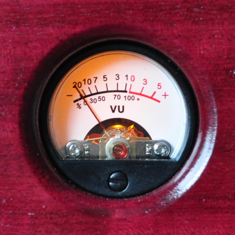
Calibration for meters like these is a two step process. The first step is properly zeroing the meters. This is done with no signal applied. On the front of the meter, at the bottom is a small screw head. Gently turning this screw moves the resting place of the meter needle. One of my meters was perfectly zeroed as delivered. The other required a slight adjustment to get the needle to rest on 0% mark on the far left of the scale. Here is what a properly zeroed meter looks like.
The second step in the calibration process is getting the meters to read out exactly 0dB with the appropriate reference voltage input. This is accomplished using the meter gain adjustments on the meter control board. These are labeled in the picture above.
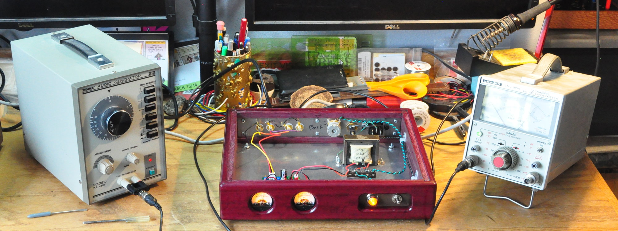
To accomplish this calibration I relied on my sine wave audio generator and a dedicated AC millivolt meter. Here is what my calibration process looked like during testing. It’s a very simple equipment setup.
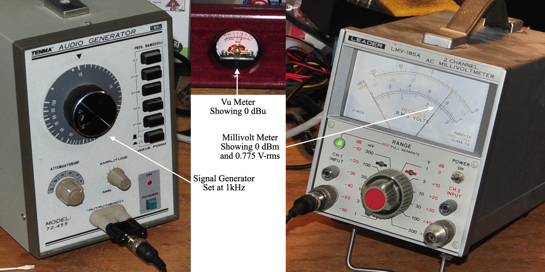
For each channel, right and left in turn, I plugged the signal generator into the input and the millivolt meter into the output. I set the signal generator to a 1kHz sine wave output and adjusted the level until the millivolt meter read exactly 0.775v. I then adjusted the appropriate gain adjustment control on the meter board to make the meter read exactly 0dB. Once both channels were done the calibration was complete.
Here is a quick closeup of the test equipment settings and a fully calibrated meter.
Once calibration was complete it was time to seal up the unit.
Summary
This was an enjoyable project and a nice addition to the 6AS7 Purpleheart SET. And as an added benefit it can be swapped out and used with any amplifier. This would also make a very good project to go between a preamplifier and an amplifier. This would help to prevent amplifier overload while still getting to use the preamp.
I’ve been using this unit with the 6AS7 Purpleheart SET since completing the project. It has allowed me to calibrate some of my audio sources and allows me just a little more insight into how everything is functioning. This was such a simple project to put together that I may build another one on a different footprint for use while testing new equipment.
So what do think of the “Purpleheart” signal meters unit?
Thank you for the thorough, detailed, and lucid instructions, along with perfect pics! I have build a pair of PASS ACA amps and have experimented with a few VU meter attempts, but all previous lacked the dynamic range to be useful. I have high hopes for your approach and have ordered the board and meter set from Amzn. I will update this page with results.
by the way, I shared a link to this page on the DiyAudio forum. Hope that is OK.
No problem.
Fantastic!
I was looking for something just like this. I’m going to build this and expand on it just a little. I would like to turn this into a main power distribution unit for pre-amp and main amp. Adding a couple relays inside and AC out jacks to supply power to pre-amp and amplifier unit. One button to turn everything on.
Easy to do. Just pay particular attention to shielding and ground isolation. Or you could buy a rank typer power panel like this: StarTech 8 Outlet PDU Power Strip
Hi Matt,
I have seven pieces of equipment that I use with the Lacewood V.2 6V6 Amp/Baxandall Tone Stack Line Amp combination. A Raspberry Pi with HiFiBerry DAC, two Braun TG1000 reel to reel tape decks, a Nakamichi 1000 cassette player, a Grundig RT50 radio, a Focusrite audio interface and a computer. I’ve built a patchboard to allow me to connect any outputs to any inputs so as to be able to record and playback as I wish. Every suitable combination can be fed into the Lacewood. I would like to build the “Purpleheart” signal meters into this patchboard. Because of the different line out voltages eg. HiFiBerry DAC 2v and Braun Reel to Reel 1v, I would like to be able to attenuate sthe line out voltages (if needed) before the signal meters so I can monitor what goes into the Lacewood. Is this possible?
This is actually very simple to do. The one thing to keep in mind is the various impedances strung together. There could be complications if you just use a passive control. A buffer would help things a lot.
I think I would suggest a 12AU7 preamp stage (gain ≈20dB), with a volume control in front of it, with the signal meters hung across the output going to the amplifier. The selector switch would go in front of the volume control. This gives you about +/- 20dB of gain cut/boost based on the volume control setting.
In this way, low inputs can be amplified and hot inputs can be attenuated. When using this I think I’d probably leave any volume control in the main amp at maximum.
Thanks Matt. I’ll let you know how the project goes. I’ll probably have to wait a couple of weeks for parts.
Nice project love it could I put this in the universal preamp or does it need to be by itself even if it’s in its own shielded section. I would like this for my lacewood amp. I have enough wood to do both. And the parts for another preamp. I use the universal preamp and lacewood every day thanks
If I were to include this in a preamp, I would likely include a lot of shielding between the preamp and the driver board. Just as a precaution if nothing else. Even though the driver board appears to be purely analog, it is conceivable that some fields could interact with the preamp without adequate shielding.
Personally, I love standalone components. That’s why I built this the way I did.
So pleased you put this up and not at all surprised in the interest everyone is showing. Looks fabulous sitting under the amp.