
A Long Lineage
This amplifier has a long design evolution history. This first prototype iteration of this design first played music on April 17th, 2011. I designed it as an outgrowth of a tube forum discussion on “spud” amplifiers (i.e. single tube amplifiers). I had stumbled across this tube in the RCA Receiving Tube Manual RC-30 and it looked like a promising candidate for a low powered spud amplifier. Here is the first prototype complete, with power transformer and tube rectification.
Whereas I found the design acceptable and pleasant to which to listen, with several other projects in the works, the design got put to the side. It was, at this point, little more than an interesting diversion.
Fast forwarding to early 2015; I had a chassis and power transformer available from The Recovery Amp and I was looking for a project. It was then that I remembered that I had used the same power transformer for the 6CY7 prototype back in 2011. I quickly pulled the old 6CY7 design off the shelf and soon had a complete amplifier built and ready to test. This version of the amplifier first played music on May 24th, 2015. So it took almost four years for that original prototype to become a real amp, but it was a great success. Here is that amp back in 2015.
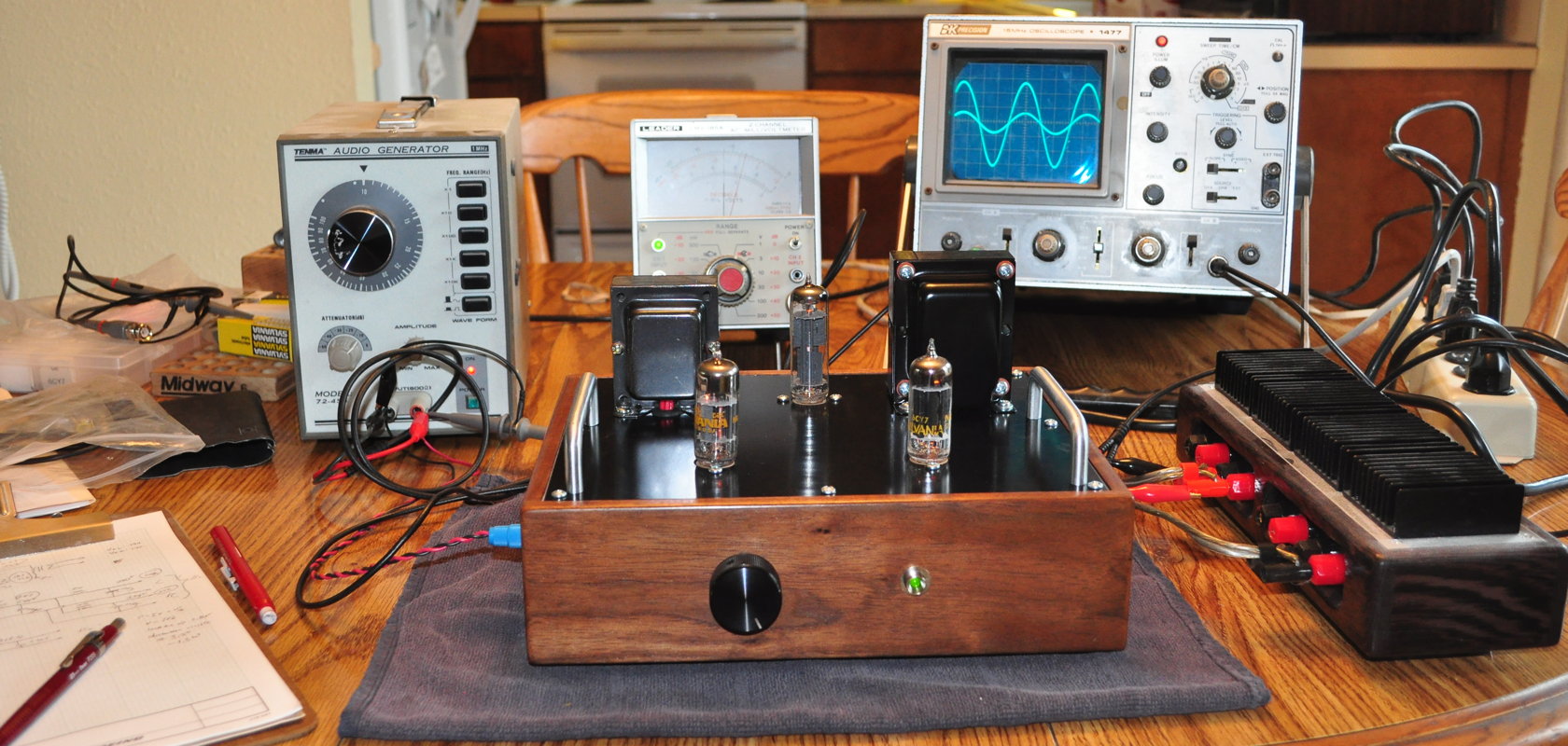
This amp became a regular performer in my office at home and a favorite of visitors to my web site. It is important to realize that I did not change my design markedly from the first 2011 prototype to the final amplifier in 2015. I changed the output transformers to the Edcor XSE10-5k and I added a little filtering to the power supply but that was it.
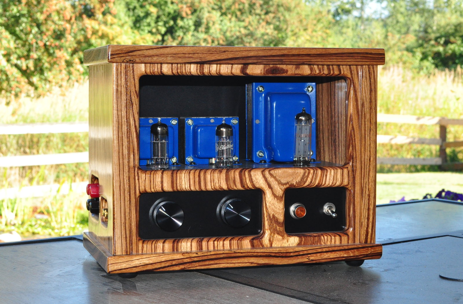
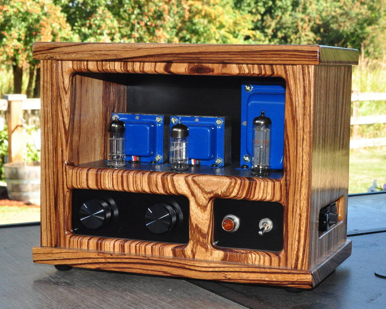
Over the next few years I received many questions and comments on the design. One recurring theme was the output transformers and if a different transformer would “improve” performance. After fielding a series of questions along these lines, I decided to revisit the design and see what could be done. The new design is based on the original with several improvements meant to help out the low end and the fullness of the amplifier’s sound. Here is the new version, the 6CY7 V2 “Zebrawood” playing its first music on August 16th, 2020.
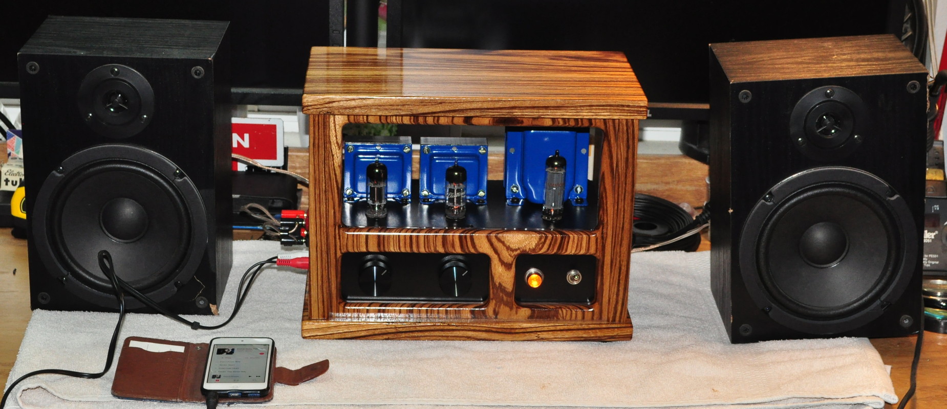
So it was a nine year journey from the first prototype to the final 6CY7 amplifier. It definetely took a while but, in my humble opinion, worth the wait. As I sit here typing, I am listening to Diana Krall performing “I Was Doing All Right” from the From This Moment On album. This amp really sounds excellent!
The Design
As I said, this was a redesign to address the low end response and fullness of the amplifier. The design is still based on the original load line designs I did back in 2011 and available on the 6CY7 page. Upon review, I decided that the basic bias points and design were appropriate for the new design, it just needed a little tweaking. Here is the modified schematic for the new amplifier.
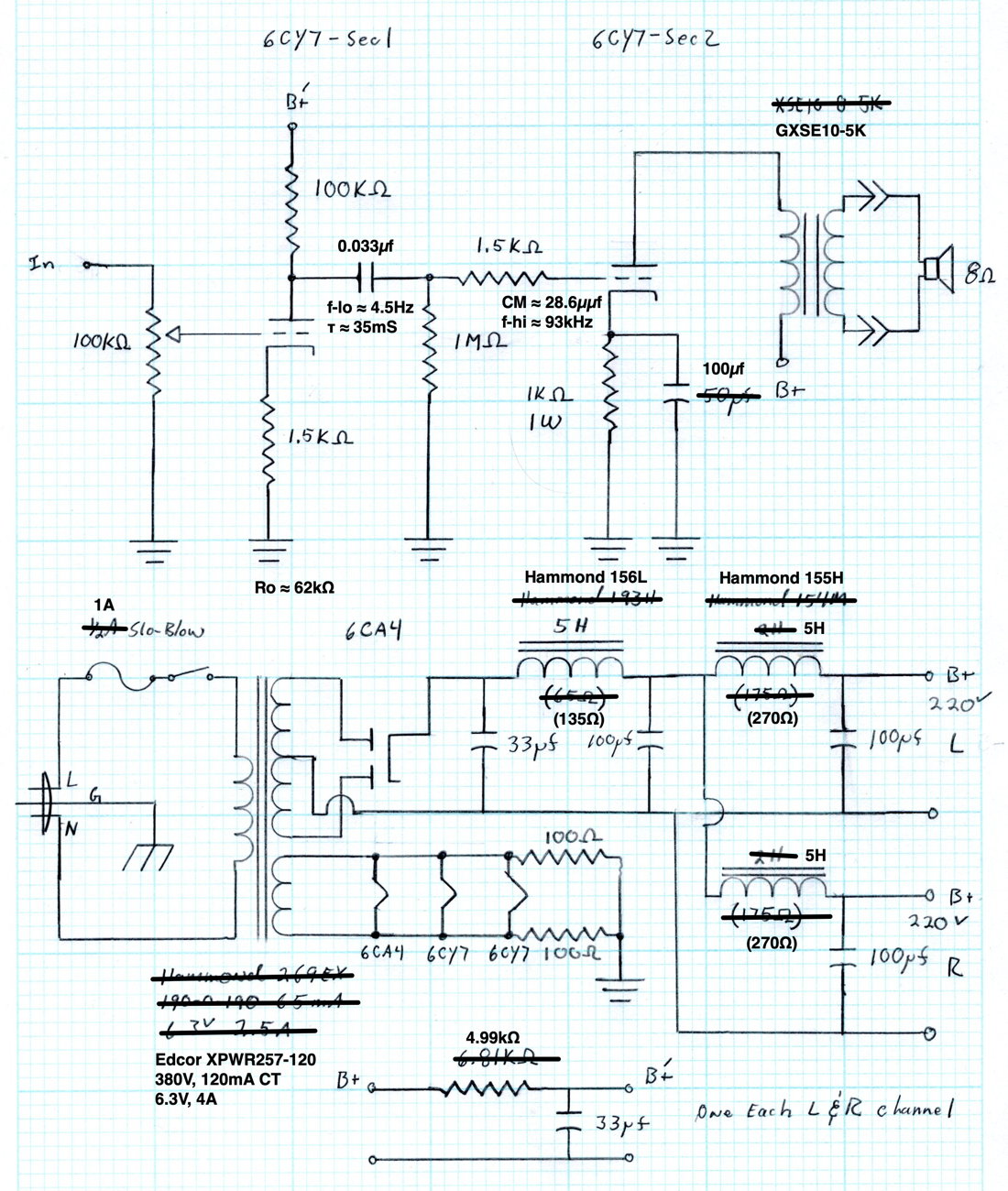
To better support the low end I have upgraded the output transformers from the Edcor XSE to the GXSE series. These transformers support better low end performance, rated down to 40Hz verses 70Hz for the XSE, without sacrificing any of the speed and detail in the design. In addition to the output transformer change, I have increased the cathode bypass on the power stage (to support better low end response) and increased the interstage coupling capacitance (also to support low end response). These changes support a better and fuller low end response without sacrificing the overall quality of the sound.
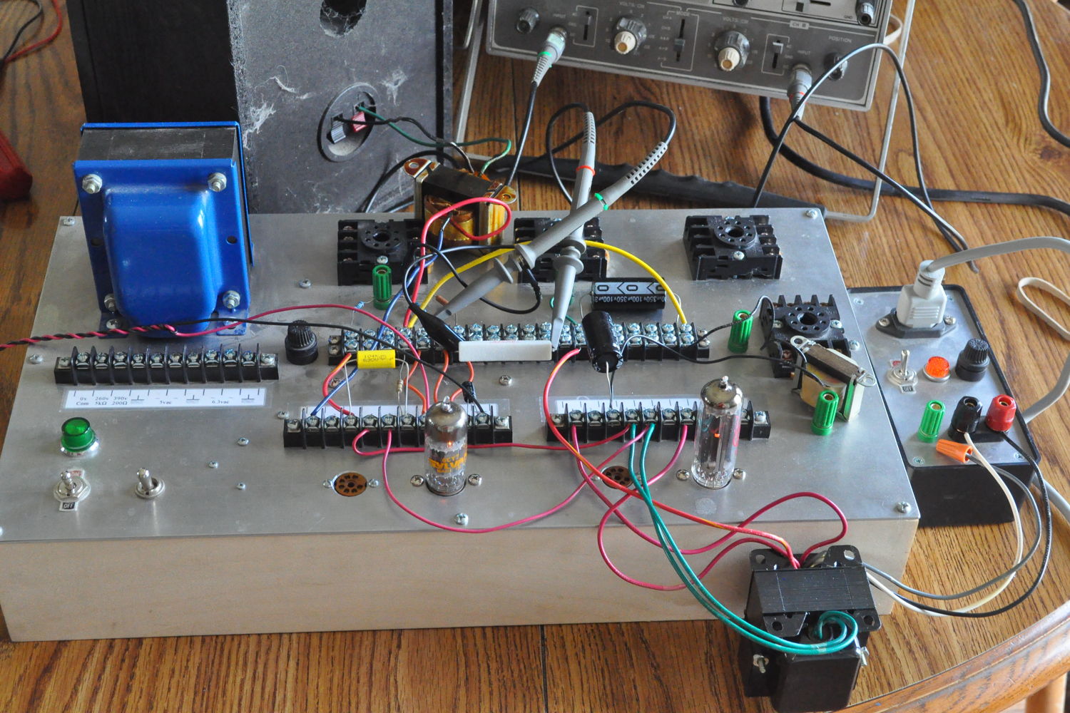
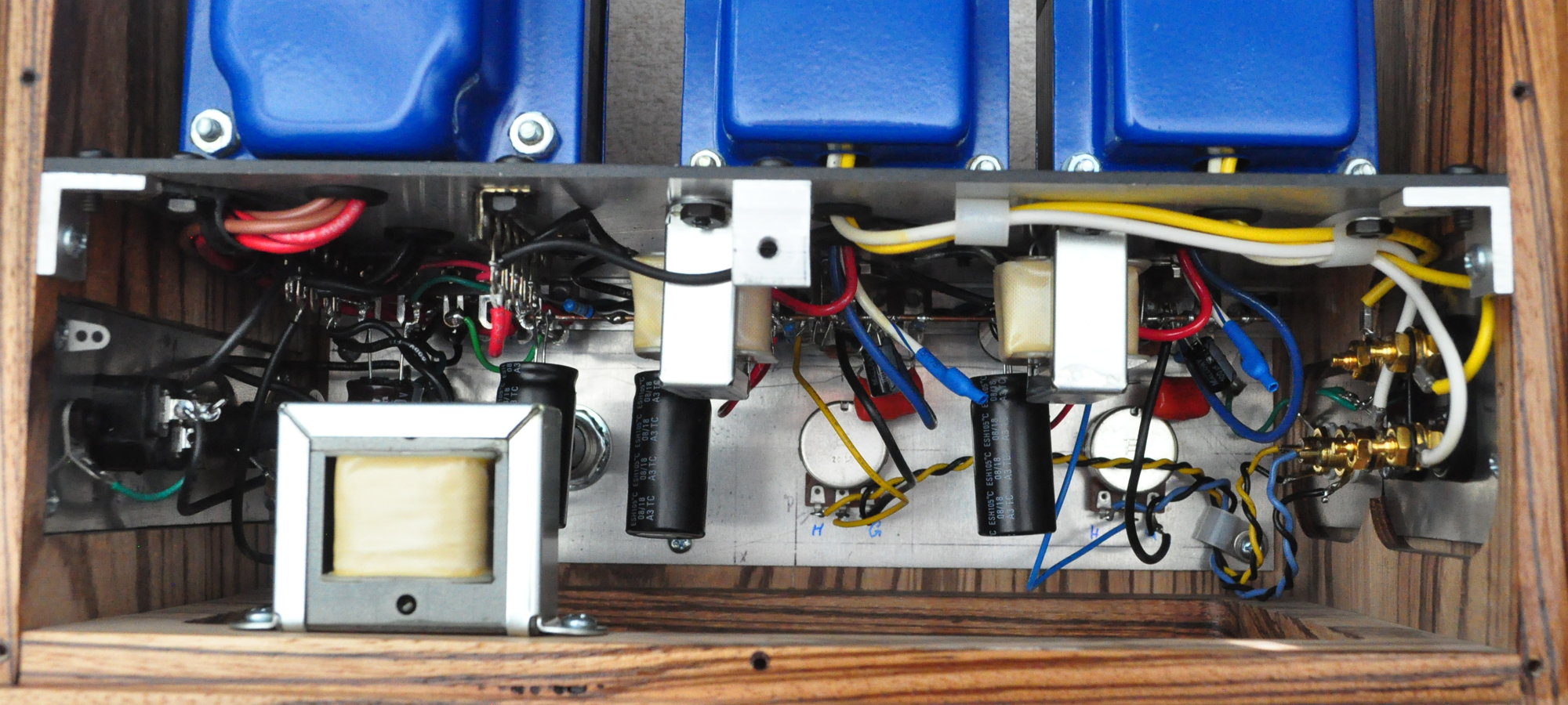
I have also changed up the power supply a little bit for better channel separation. And finally, I chose to use an Edcor power transformer for this build as it stays much cooler than the Hammond. I wanted this characteristic because the the chassis design places the transformers in a wood alcove and I didn’t want to thermally stress the wood any more than necessary. Additionally, the added filament winding capacity allowed me to use a jeweled indicator on the front of the amp (with an intensity limiting dial). Here is a picture showing the main plate all wired up and ready for installation in the chassis.
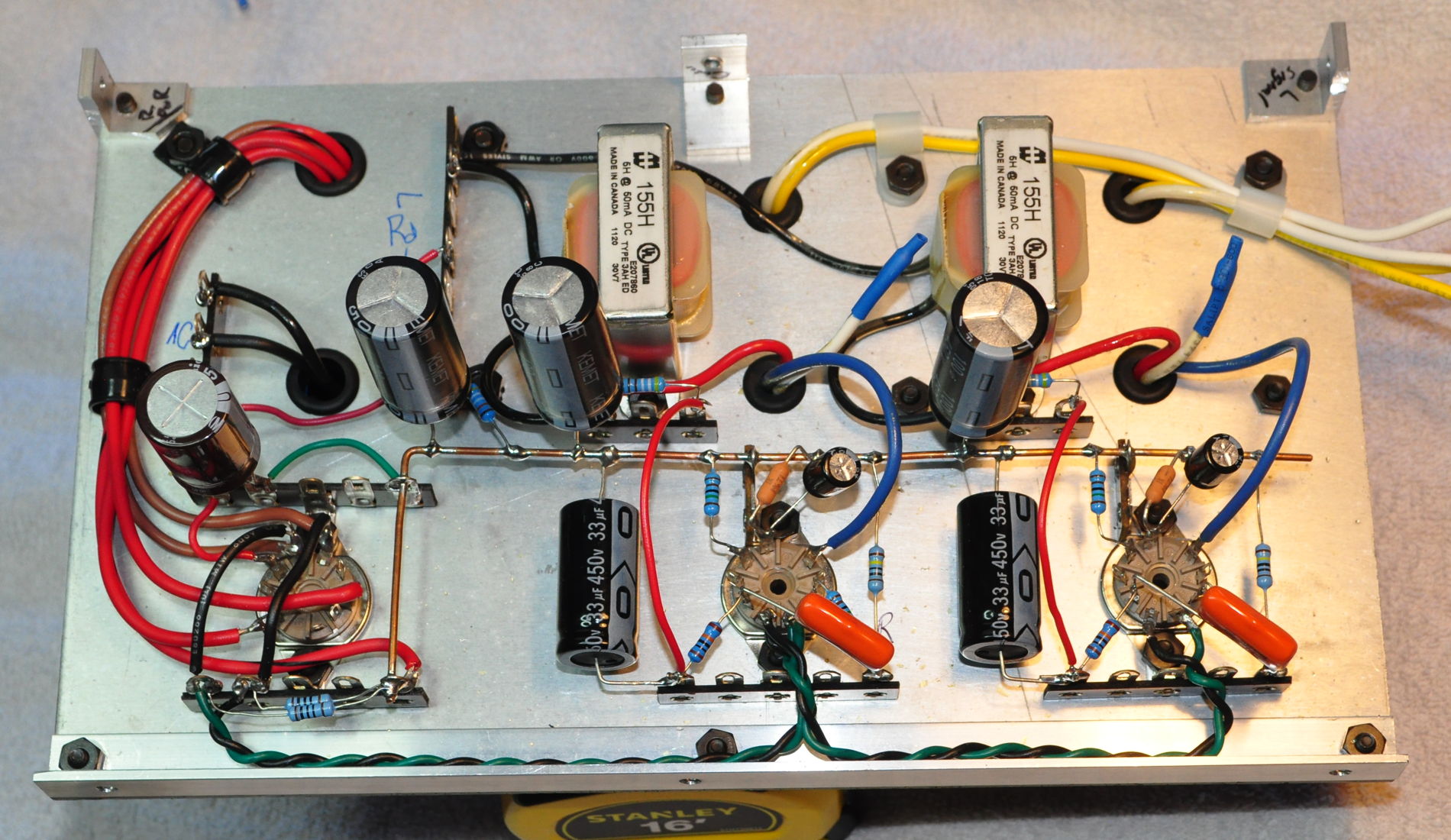
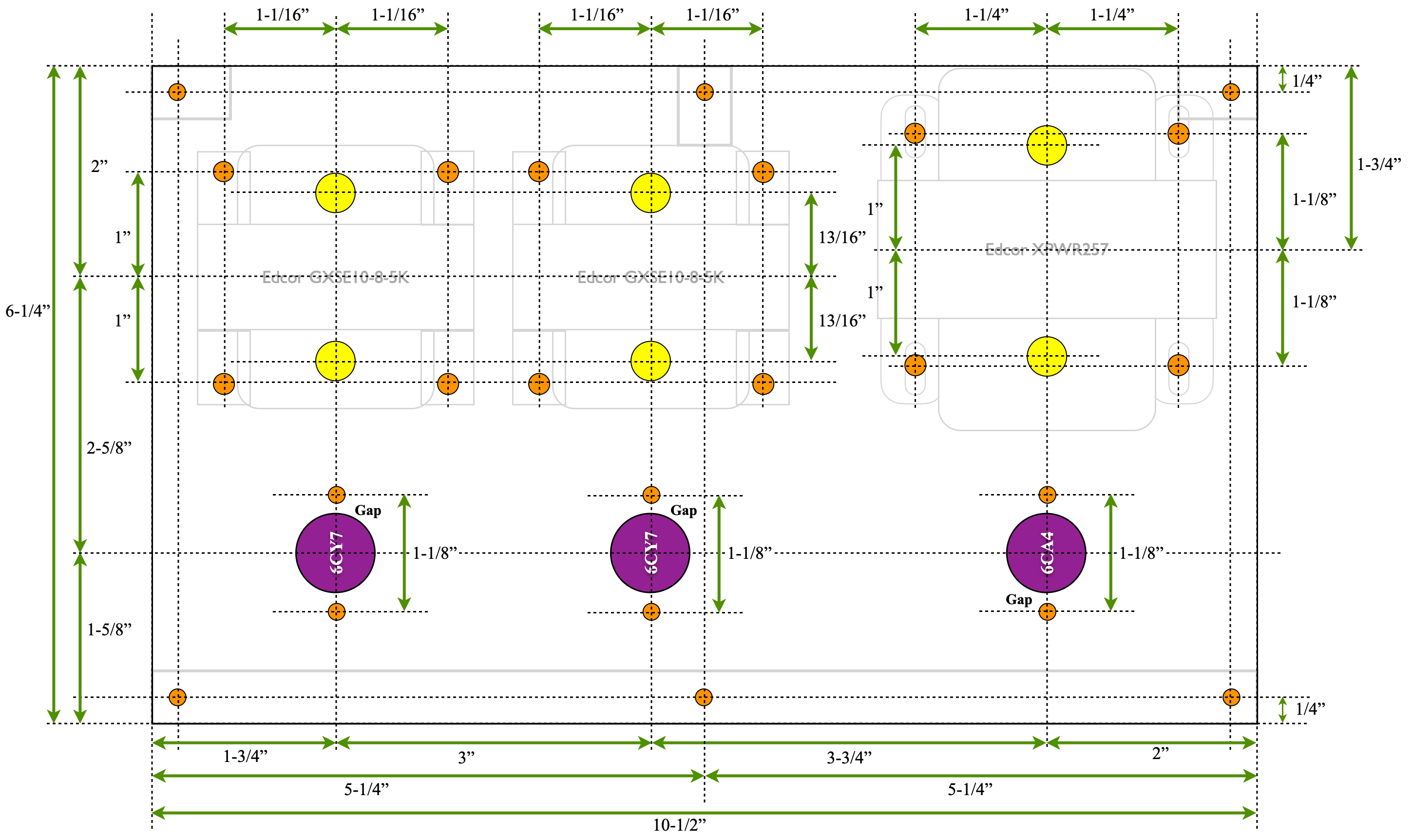
This is deceptively simple for a full stereo amplifier. The main power supply is to the left. The individual channel power filters are mounted above the ground buss underneath the output transformers. And the two signal stages are below the ground bus adjacent to the power filters. This aluminum plate is only 10 1/2 inches by 6 1/4 inches. Here is the measured drawing showing the layout.
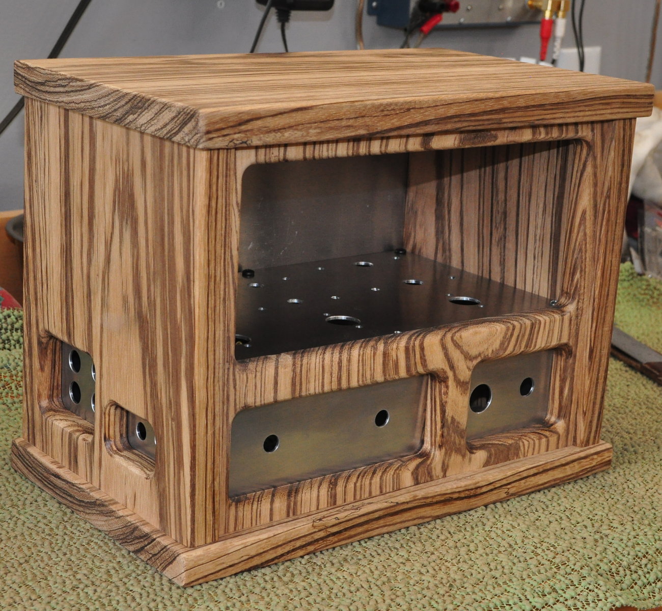
The chassis for this amp is based on a “wrap around” design with a large window in the front to showoff the tubes and transformers.
In addition to the usual layout features, I have included a new feature on this amplifier. One of the major problems with spud amps like this is mismatch in overall gain between channels. It is not always possible to get pairs of tubes that are well matched and this means the volumes can vary between channels. Because of this, I decided to add separate volume controls for the left and right channels. This ensures that I can always adjust for variations between tubes and for room acoustics as well.
Testing
As the goal was to “improve” the low end frequency response of the design, I decided to run this amplifier through what has become my “standard” set of testing. First off, peak output power for the amp was about 1.25W based on waveform observation on the oscilloscope. Distortion numbers at two power levels, high power and moderate listening, are shown below.
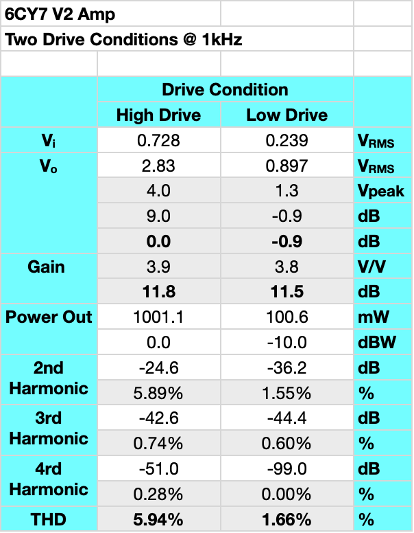
The distortion level is a little above the typical 5% target level at 1W but it is virtually all 2nd harmonic, as is the distortion at 100mW. I consider this good performance for an amplifier of this type.
The obvious question at this point is did I really improve the low end as desired. The band pass was definitely improved. First, here is the band pass of this amplifier.
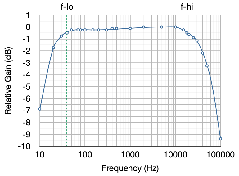
The amplifier is only off by 0.50 dB at 40Hz, 0.76 dB at 30Hz, and 1.76dB at 20Hz. This is not only good performance, but it is a significant improvement over the original design. Here is the same bandwidth plot with the frequency response of the 2015 amplifier overlaid for comparison.
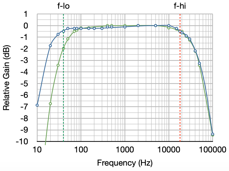
The high frequency response of the amplifier is almost identical. This rolloff is almost entirely due to the output transformers with both the XSE and GXSE being just about 1/2 dB down at 20kHz. The low end response is significantly better in the new design. The relative improvements over the 2015 design are 0.91dB @ 50Hz, 1.46dB @ 40Hz, 2.66dB @ 30Hz, and a full 5.0dB @ 20Hz.
When I A/B tested the amps, the improvement in the low end was very apparent. In addition to the frequency response, the distortion at the low end in the new design is also significantly reduced yielding an even cleaner sound.
Impressions
Like the first version, this new amplifier sounds excellent. The sound is fast, detailed, and very clear. And whereas the first amplifier had a low end response that was full and well controlled, the new amplifier takes that response to the next level with more muscle and fullness. This is a definite upgrade to the first version.
If you were thinking about building the 6CY7 amplifier you should build this version. This is one of the best spud amps I have ever heard. So let me know what you think of the V2 upgrade.
I’ve been listening to this build for a weeks now. I really didn’t know what to expect as this was my first “spud” build. I suppose I was expecting a rather thin sound. That is not the case at all. This thing has some serious low end. The kick drum in a rock song is incredibly powerful.
It may not be may favorite all-around amplifier, but it has sound I really like for rock and live performance music.
Also, driving the tubes near full output (which is possible given their modest output rating), gives the music an interesting texture. Again, I think it really compliments rock.
For anyone on the fence about this build, fear not, it sounds fantastic.
Hi! Two questions: what is the small section that says “One each L&R channel” on the schematic? Where does it tap in?
2) where does the jewel LED come off the transformer? I do not see it in the schematic.
This 4.99kΩ/33µf LC filter is used to provide additional filtering to the B+ supplied to the signal sections. They tie in to the B+ for each channel.
The lamp for the jewel power indicator is wired across the 6.3V filament winding. It is not shown on the schenatic. You can use either a #44 or #47 indicator lamp in a standard holder (like a Fender style indicator).
Thanks for that clarification! I appreciate it. Looking forward to building this!
Hi Matt,
Can use 0.047uF instead of the 0.033uF ?
Many thanks !
William
Yes. A 0.047µf will work fine for the coupling capacitor.
Thank you Matt !
Hi Matt,
Just an update: Tonight I have tested the power supply. As load for power triode I have a 7k5/10w resistor and for the driver triode I have a 220k resistor. I got 219v for b+ and 209v for b’+. In between I have a 10k resistor. It looks like 209v is a little too low so I’m thinking to change the 10k resistor with 5k6. That should give me around 213-214v for b’+.
All in all I’m happy I didn’t blow any fuses.
Hi Matt,
2 more questions please,
1. I have all my power supply caps at 250v. Psu2 shows me the first cap (33uF) is at max 237V. But now I’m getting nervous, bc I see you are using 400v. Is 250v enough?
2. Where do I tie the two grounds? The amplifier ground and the mains ground(green wire). Should I do it at the rectifier’s first cap?
Thank you.
In this design, the steady state voltage at the cathode of the the 6CA4 rectifier is approximately 240vdc. All the other power supply voltages are between 220vdc and 240vdc. With capacitors rated at 250vdc that provides only between 4% and 12% design margin. I’m not comfortable with such low levels of margin in my designs. I prefer at least 20% margin minimum. I suggest resourcing your filter capacitors for some rated at at least 300Vdc.
Tying the chassis ground to the signal ground at the first filter capacitor should be fine. In this design, where the chassis ground and signal ground are tied together is not that critical. I have a full discussion of my grounding philosophy at this link: Grounding Philosophy
Thank you very much Matt
Hello Matt,
I have some questions about V2
1. Instead of the 100k pot, could I use 1M resistor from input to ground? I have a preamp.
2. I’m not questioning your schematic, I’m questioning my lack of knowledge: should I use a 1.5k resistor to the grid of first triode as well? Same as the second triode?
3. I’m planning to use cxse5-5k-8 as output transformer. It’s only 5w. Will this work?
It has wider range of frequencies.
Thank you
I’ll take your questions in order.
About the volume potentiometer. Do not eliminate this control. This is a relatively sensitive amp. It only requires 1.16V peak or about 820mV rms to drive it to full power. The signal stage is only biased at ≈1.3V. Without the input volume control it would be very easy to overdrive the amplifier even with normal line level signals. With a preamp in front of this amp, you are virtually guaranteed to end up severely overdriving the signal stage. Install the volume control, choose a setting that works well in your setup, and leave it alone. Better safe than sorry.
I don’t install a grid stopper on the driver because it’s highly unlikely to be needed. The power stage will overdrive first and the top end is not so high frequency for me to want to form a lowpass filter with the Miller capacitance of the driver section.
The power stage is only biased at 29mA. The CXSE5-5K is specified for a maximum bias current of 40mA so you should be fine with that output transformer. I doubt that you will notice any bandpass difference between the GXSE10-5K and the CXSE5-5K. Yes the CXSE is rated up to 20kHz, but this amp is only about 0.5dB low at 20kHz with the GXSE. Any improvement the CXSE might provide will be inaudible. But the CXSE5 IS significantly less expensive than the GXSE10. So definitely save some money and use the CXSE.
I hope this helps.
Very helpful Matt. Thank you.
hello Matt, on the 6CY7 amp, if i decide to do dc filament heating using separate 6.3volt iron, do you have to ground the negative return by connecting to the virtual ground of the two 100R resistors? or dc heating is not really going to improve the sound quality? thanks. Gene
I’ll take the second question first. The use of DC filament voltage will have no effect on the audio quality when using tubes with unipotential cathodes (as most receiving type tubes have). Twist the heater lines to limit the magnetic fields and you’ll be fine from a noise perspective. I only use DC filament voltages when building signal chains with directly heated triodes.
When you do use DC on the filaments of DHTs, in general the negative side should be connected the cathode load with the positive side floating. Note that this will increase the effective bias voltage by one half of the DC filament voltage.
thanks much Matt. earlier i did get the Rod Coleman dht kit for my “26” linestage project & he does go into that in depth. the amount of heatsink space those tiny pcb’s /mosfets take up is incredible! i also learned a lot about using X2 safety caps & the pulses emanating from the xfmr leads & why they should be as short as possible.
Hi, I live in a European country and would need to replace Edcor XPWR257-120 transformer with some other transformer that will convert the voltage from 240V instead of 120V. Could you please advise me?
My first recommendation would be the Hammond 369EX which is the universal primary version of the power transformer I used for the first version of this amplifier. But note that if you use this transformer there is not enough filament current capacity to add the #44 or #47 panel lamp.
hello Matt! many moons earlier when i saw the 1st version of the 6CY7 amp, i did prototype with the 269EX iron on a wood cigarbox.with 3 valves in tow it is taxing the tiny xfmr with 2.5A fil. rating. i also thought about doing dc supply wth separate 6.3v winding.the Edcor mains xfmr has plenty leeway. i really like the simple, precise layout of the Zebra version. and i happen to have some 6″ x 12″ coppersheets & if you’d like to share the machinist who punched for you it would be great. hey, you didn’t have a relative who perished in Ukraine earlier did you? thanks & take care
I really like my 6CY7 Zebrawood. It’s a nice option for listening in my office while I work.
As for the metal work, I do all that myself in my workshop. I talk about working with the copper plate in this blog post: “Pecking” at the SET.
Hello!
First time builder, and I can’t wait to try this out!
Would it be possible for you to share the parts list?
Hello Matt,
Great Look on this amp,
Your wood-working skills are getting more & more impressive !
After my very rewarding builds of the 6V6 Marblewood & then the 6336 “The Beast”
I have been looking for a SE Pre-Amp schematic for a while and of course your universal Pre-Amp is a fine candidate.
But I was wondering if you could tweak the 6CY7 V2 in order to turn it into a stand alone Pre Amp. ie. with a 2 stages gain instead of the 1 stage gain in the Universal.
At this point, I have a few questions regarding pre-amps :
– Is the 2 stages gain overkill in a Pre-Amp ? I guess it depends on the type of tube used…
– Is there any improvement in channel separation when you allocate one double triode per channel (2 successive gain stages such as this amp) as opposed to sending the L and R channels through only one double triode (1 gain stage such as the Universal) ? I am not sure I make myself clear…. Hmmm
– If it is feasible, how would you adapt the input & output impedance of this circuit ?
Thanks for your comments, as usual, very informative.
There is really no need to place multiple gain stages into one preamp unless there is some significant loss in the signal chain, such as a set of tone controls. As to changing the 6CY7 design to act as a preamp, it’s possible, but there are many better ways to get a good quality preamp. The 6CY7 tube would not be my first choice. The channel separation gained by isolating individual channels to single tubes is usually not worth the effort. With proper layout and design having both channels in one tube envelope is not an issue.
Hello Matt,
Thank you for a very clear answer as usual.
Your 6336 design shows how well a single tube can handle both channels.
Christophe
Ok I’m convinced. I want, no need to build this. Lol
But this would be my first build.
Is there a component list?
Also any prefab housing available somewhere that can be used?
Yes there is a parts list. I’ll email it to you.
As for the chassis, I suggest one of the little Hammond enclosures like the 1444-24. This is a 12″ x 8″x 3″ aluminum chassis that should have plenty of room for a first build. They are easy to work with and come in a variety of sizes and finishes.
Thank you so much Matt!
Quick question:
Where did you get the volume control knobs? Do you have a part number for them? I like their “look”.
Thanks,
Dave K.
I bought them at Antique Electronics Supply.
OK,
Thanks!
I was all set to build V1 when V2 appeared. I had even determined to start “one day soon”. The case and plugs were done and the Hammond transformer acquired long ago. I’d planned to use GXSE output transformers anyway and the resistor change is of no concern.
However both chokes have changed apparently significantly. I admit having no “feel” for these, not knowing if Henry value, resistance or current limits count most.
Obviously I’d like to take advantage of improvements but I don’t fancy buying more chokes if possible. So, can you recommend alternative chokes which might offer some improvement yet there is a chance of me finding in my growing selection of spares. Choices of choke seem fluid compared to other components.
Mark
You can use the original 193H and 154M chokes in the V2 power supply. The switch from the 193H to the 156L was just due to chassis constraints and the shift from the 154M to the 155H was to match the mounting provision in my new design. The channel separation will still be excellent with the 2H chokes. Frankly, the 5H chokes in these positions may be a little bit of overkill. I recommend using what you already have.
OK, got that, thank you. M
Matt,
I have built your designs in the past with great success. I have a question about V2.0. Could you use something like a balance control in place of the two volume controls and then a master volume control? How would the Pot values change in this set up if even possible? I guess that’s two questions. As always I look forward to your response.
There are two main issues with balance controls, insertion loss and impedance matching.
The passive balance control will always act as a voltage divider between channels. This means that at the neutral setting (i.e. “balanced”) there is an insertion loss for both channels. And the more definition you want in the control, the higher this loss. For “acceptable” levels of control performance the insertion loss is generally between 4 and 6 dB. This is a loss that needs to be made up in the signal chain somewhere.
The other issue with the passive controls is that they need to be driven by a fairly low impedance and they need to be loaded by a fairly high impedance. In two stage amplifiers like this one, I would be tempted to leave a dual ganged volume control in front of the signal stage and insert the balance control between the signal stage and the power stage so I could handle the impedance problem. The only issue then would be the frequency response because as the balance control is moved, there are different loading resistances on the coupling capacitors and as seen by the input Miller capacitance.
In a different topology I could come up with some reasonable solutions. But to really make it function well would required the addition of a signal stage in each channel. This would really defeat the purpose of the dual “spud” amp topology.
Does this answer your questions?
Yup. It answers my questions. Thanks as always Matt.
Could you replace the individual volume pot with a dual pot, wired such as one channel goes up the other down, effectively acting as a balance? Of course that would limit max volume.
This is possible but difficult to do properly. First you need a speciality dual control, one with an “A” taper and the other with a “Reverse-A” taper. These are VERY rare if you can find on at all. The second issue is at the middle setting (i.e. with both channels at equal volume) the control has a nominal 20dB loss.
It would probably be better to wire one dual gang volume control and once “balance” control. But the balance control would also insert about a 6dB loss. Which is still a lot for this little amp.
Matt,
Along the same lines of a single dual volume pot. I was thinking of changing the 1K cathode bias resistor on the power section of the 6CY7 to a potentiometer? Then be able to dial in plate dissipation on individual tubes to more closely match and keep a single volume control. How would this effect the performance of this amp?
I wouldn’t really recommend this. The mismatch in amplification is generally in the signal stages and not the power stages. And as much as the dual volume pots give that balance flexibility, they really aren’t required in most cases. You’d actually be better just buying 4 or 6 6CY7s and if you get a channel that is out of step with the others, just swap tubes.
Where is the Hammond 156L mounted? I can’t see it in any of the pix.
I wondered when this question would arise. It seems that I again fell into the trap of making the chassis just a little bit too small. As such, the 156L primary filter is mounted on the bottom of the chassis under the power supply section.
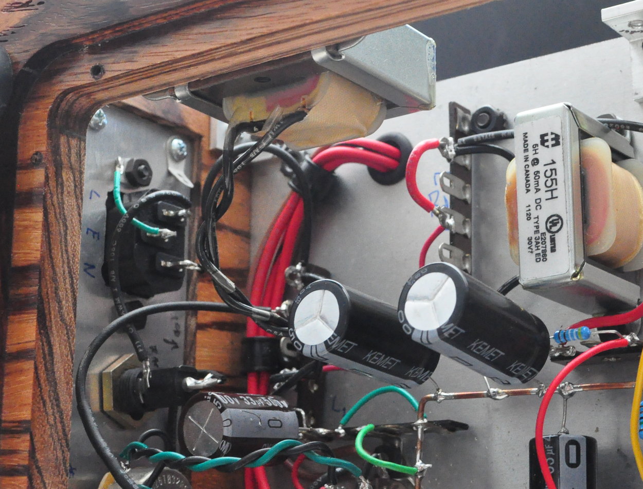
You can see in the picture below how it is wired into the leftmost terminal strip where you can see the “L1” written on the bottom of the main plate (between the 33µf and 100µf filter capacitors).
I hope this makes things a little more clear.
Looks really nice!
I like your under chassis layout, especially the heavy gauge B- bus, very convenient too.
UL Listed filter chokes – a nice touch. Is the Edcor power transformer listed also?
A question about the rectifier. I see you have been powering the rectifier filament from the same 6.3 volt winding as the other tubes. Any concern or problems with the very high heater to cathode voltage of the rectifier?
I have seen several Mullard designs with a separate 6.3 volt winding powering the 6CA4. Mullard was concerned that the rectifier’s H-K voltage could potentially cause issues with the other tubes due to their lower H-K voltage rating. Just asking.
The 6CA4 is a true
filamentaryunipotential cathode tube. The rated maximum heater-to-cathode voltage (heater negative with respect to cathode) is 500V. The filament circuit is held near ground (+/- 3.15v) by the virtual center tap formed by the two 100Ω resistors. I measured the cathode voltage in this design at ≈240v. So the rectifier design is only at ≈48% of spec so I think it’s ok. As for the other tubes, the virtual center tap should prevent problems with any of the other tubes.Yes 48% is well within the 80% of max rating “rule of thumb”.
Would you see any advantage to silicon diodes over tube rectifiers?
No. Frankly, I just don’t like solid state rectifiers in tube circuits.
The B+ comes up too fast and without tube draw you get B+ overshoot which stress everything in the circuit. You can get pops, thuds, and other problems. You really have to us UF diodes to avoid the horrible hiss solid state rectifiers induce. I just don’t see the point. Vacuum tube rectifiers are cheap, plentiful, easy to use, and they allow the B+ to come up at the same time as tube draw increases so the B+ voltage doesn’t get out of hand. I especially like the slower warm up rectifiers like the 6CA4 and the 5AR4/GZ34.
OK,
Thanks
I usually use the term indirectly heated. But yes tube data sheets use the term unipotential.
The reason I like these (unipotential cathode rectifier tubes) is that they take longer for the emission levels to come to a quiescent state. This means that the other unipotential receive tubes are also coming up at the same time. This provides for a much smoother startup sequence with little if any B+ overshoot. You can add the little 6X4 to this list as well.
Yes, understood.