
A Different Kind of Project
This project started out a little differently from most of my projects. Most of the projects I build are dedicated units; amplifiers, preamps, headphone amps, etc. But this project was designed to fix a specific problem I was having in my office setup. The issue I was having was easily swapping between the various sources in my office system. I had a simple switch for just two sources, but the number of sources was growing and I clearly needed a more robust solution.
There was also the issue that the various sources each had different output levels. This meant that every source change required me to rebalance levels at different points within the system. I really wanted a single unit which would allow me to select the source, adjust the level the way I wanted, and to provide feedback on what was going to the amplifier. So this unit, a “Source Selector Preamp” or SSP, was designed with these goals in mind.
Requirements
As much as it would be great to dive right into design, I knew I needed to clearly record what I wanted or I wouldn’t be able to keep myself on track. This meant I needed to record specific requirements and formulate an architecture before I started.
The first requirement was source selection. I already knew what it felt like to have an insufficient number of inputs so I decided I’d have six selectable inputs. This is enough to cover the computer, cd player, DAC, tuner, Bluetooth receiver, and a spare. This should provide enough flexibility to avoid any cable switching on most occasions.
The next requirement was level adjustment. Each source supposedly has a “line level” output. However, the reality of the situation is that the sources have as much as 10dB of variation in output voltage. And some sources have different average outputs based on the music. For instance, both the DAC and the CD player outputs can vary greatly based on the digital mastering of the CD or digital audio file. This meant I needed a level adjustment function.
The form of the level adjustment was important. I didn’t just want a volume control but rather a control that made sense in the context of the SSP itself. I decided that a relative level adjustment function would provide what I wanted. This adjustment would provide a mid-level reference which equated to unity end-to-end gain (i.e. 0 dB) at the half way point and provide roughly equal amounts of voltage boost or cut dependent on its relative position. A typical audio taper volume control provides ≈20dB of signal attenuation at the midway point, so an active gain stage with 20dB of gain (end-to-end) would perfectly offset the volume control and give my the functionality I wanted. This set the overall active gain at approximately 20dB.
The third requirement was that I wanted to be able to see and monitor the magnitude of the signals being provided to the downstream amplifier. This would be feedback for the level adjustment function so as to avoid over or under driving the amplifier. It also means that once the amplifier listening volume is set, if I switch inputs, adjusting for the same output with the level adjustment returns me to the same listening level. This way the only time I adjust the amplifier volume is if I really want the music louder or quieter in my office. I decided to use the same type of level indicators I had used for the “Purpleheart” Signal Meters project. These meters are easily calibrated to show actual signal voltage levels.
A fourth requirement was that I wanted this unit to be able to drive either a high input impedance vacuum tube amplifier or a lower input impedance solid state amplifier. This meant that I needed to include a buffer stage on the output with a low enough output impedance to handle the load of the signal meters in parallel with downstream amplifier.
The Electrical Design
The requirements I’ve listed mean that the architecture has several stages. These include a selector, a level adjustment control, an active gain chain, and a low impedance output buffer. The architecture looks like this.
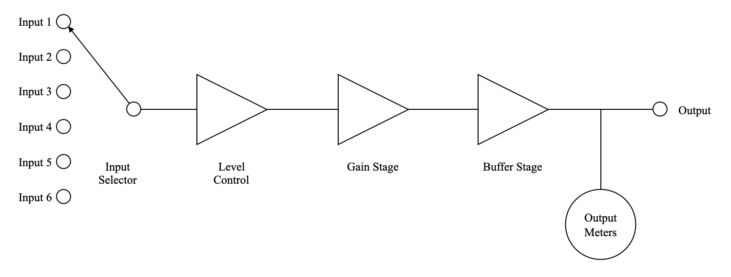
The order of the stages in this architecture is intentional. Placing the level adjustment in front of the gain stage assures that gain stage overdrive will be rare because the nominal loss of the level adjustment is -20dB. A 1v-rms signal applied to an input will be reduced to 0.1v-rms (at the mid-level setting) before being applied to the input of the gain stage. This helps to prevent inadvertent gain stage overdrive and it minimizes the gain stage distortion by lowering the voltage swing. It also means that the amplified output of the gain stage will be far less likely to overdrive the buffer stage.
The input selector is a simple switch and the level control is just an audio taper potentiometer. The gain stage and the buffer stage need a total gain of approximately 20db to meet the unity mid-level gain requirement discussed above. The buffer (a cathode follower in this design) will likely have somewhere around a dB of loss. This means the gain stage needs slightly more than 20dB of active gain. The buffer stage also needs a low enough output impedance to handle the parallel combination of the meter input impedance and the lowest input impedance of any amplifier driven. So this architecture is now driving new requirements on some of the components.
Turning to the gain stage, I wanted a simple design with a gain of somewhat over 20dB. I also wanted something with a sufficient input bias that it was unlikely to ever be overdriven even it the level control was turned all the way up. Luckily, I had already designed such a gain stage for the 12AU7 Color Preamp. Here is the load line for the final gain stage design.
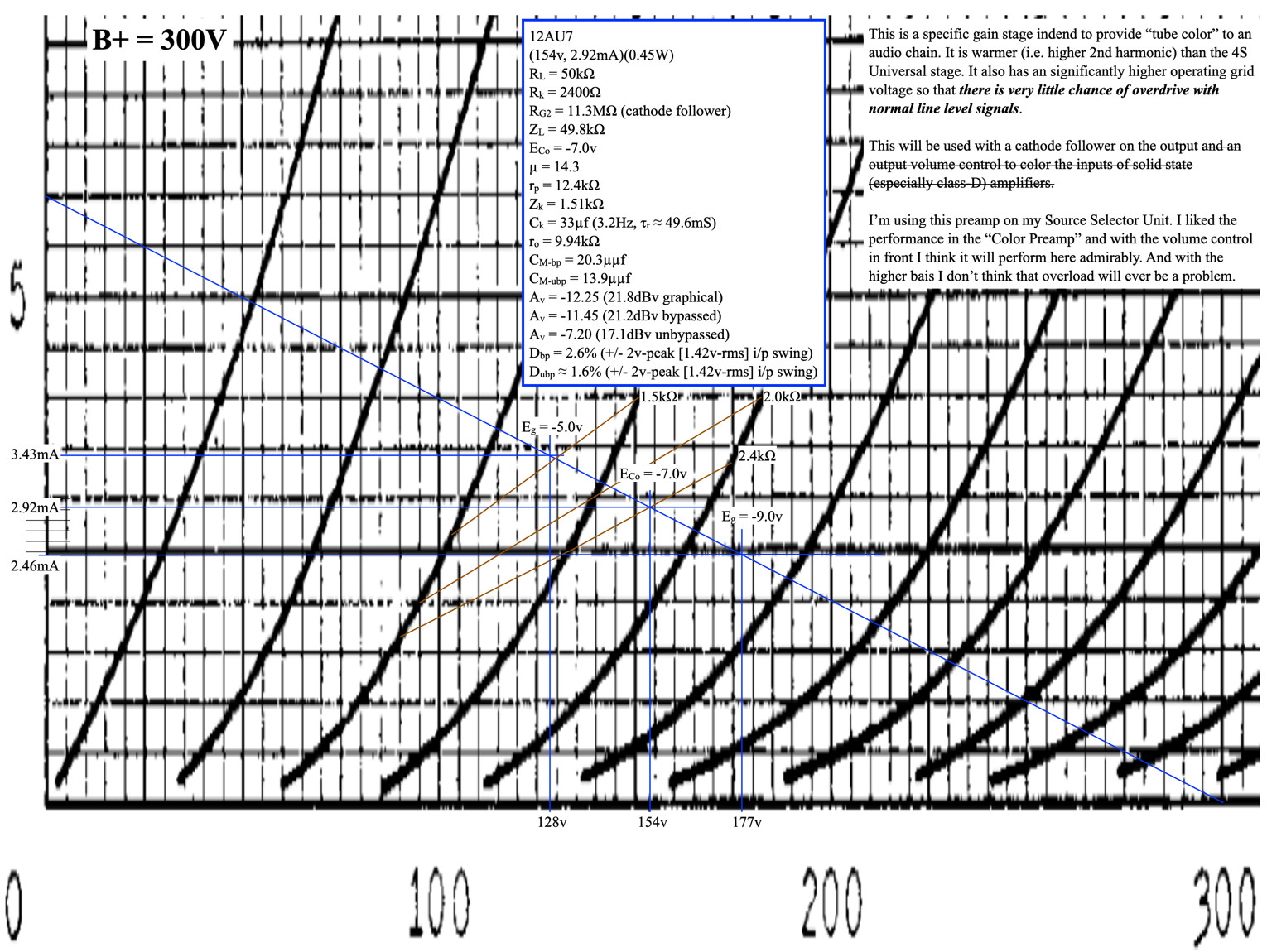
The final gain of this stage is ≈21dB so it should wok out for the overall gain needs. The bias voltage is 7v so it would require an input voltage of ≈4.9v-rms to overdrive the stage. With the level control in front of it, overdrive should be virtually eliminated. And with a nominal input voltage around 0.2v-rms (i.e typical line level minus 20dB) the distortion should be at or below about 0.25%.
The buffer stage used in this design is slightly different than the one in the color preamp. In the color preamp the allowable input voltage swing to the cathode follower was a major driving requirement due to the placement of the volume control in that design. In this application the input voltage to the buffer will be control to be nominally a “line level” voltage. As such a slightly different design could be used that has excellent performance even driving very low impedances (down to ≈10kΩ). Here is the load line for the final buffer design.
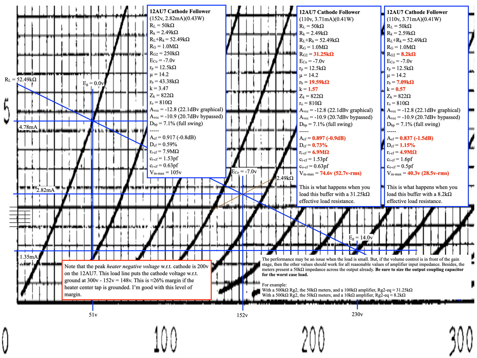
The text box to the left contains the performance parameters for the basic buffer design. The two boxes to the right show the performance when loaded with the combined parallel loads of a 500kΩ fixed resistor, the 50kΩ meter board input impedance, and two different amplifier impedances; 100kΩ and 10kΩ. The nominal insertion loss is about a dB, the distortion is very low, and both situations allow a large input voltage swing.
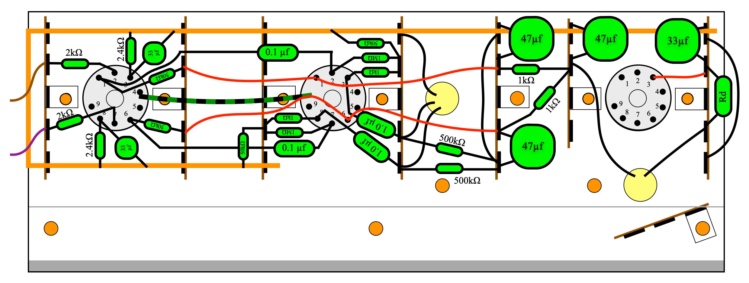
The final electrical design for the preamp, including the power supply, is shown below.
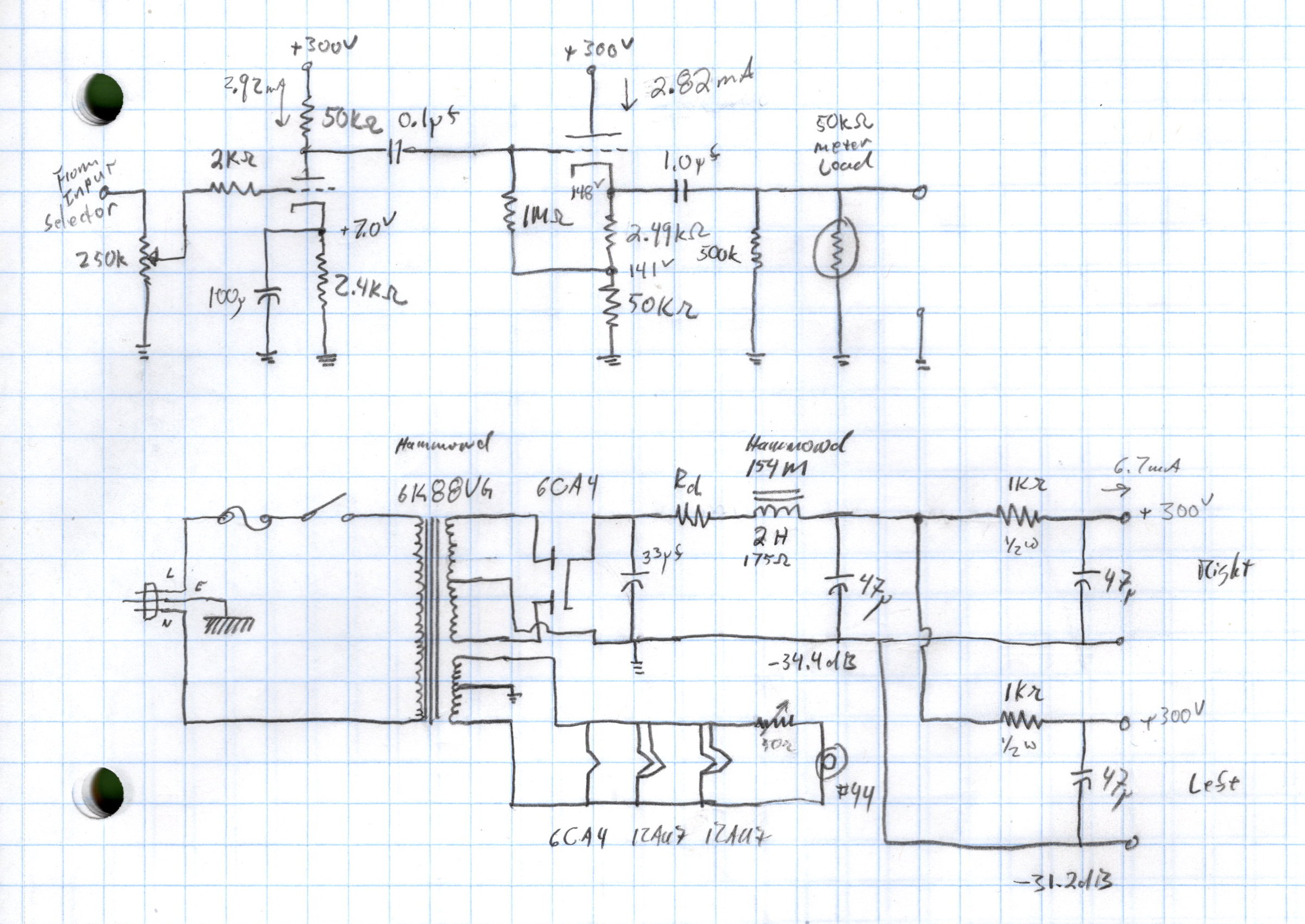
There is something missing from this schematic. That’s the power for the meter board. The meter driver board that I decided to use is the same one I used in the Purpleheart Signal Meters project. This board requires an AC input voltage between 12v and 18v RMS. I decided to use a simple 12.6V 1.2A filament transformer which was already in my parts stash. This transformer provides the power to the meter driver board and also drives the panel lamp for the unit. This is true even though the panel lamp is shown connected to the main transformer filament winding in the schematic above.
The Build
The physical form of this project was also going to be a little different from my normal projects. In most of my projects I aim to highlight the tubes. Either by mounting them on top or in nice viewing cubby holes. But this unit needed to be physically different. It needed to stack with some other standard size components including my Cambridge AXC35 CD player. This meant that all the electronics need to be mounted inside including the vacuum tubes. It also meant that It needed to have ready access in case of tube failure.
I started by setting the external dimensions of the unit. Width is 17″ to match my CD player and my tuner. The chassis depth is 11-3/4″ which is close to the depth of my CD player but deeper than my tuner. The overall chassis height, not including the rubber feet, is 3-1/2″. This size gives ample room for everything that needs to go inside the chassis and still leaves room for signal isolation and ventilation.
The chassis wood I chose was a piece of African Bubinga (Guibourtia spp.). This is actually the same piece which was in the running for the 6AS7 “Purpleheart” SET Amplifier chassis. Here it is just prior to running it through the planer.
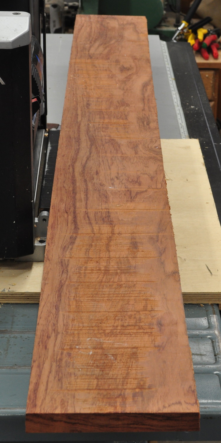
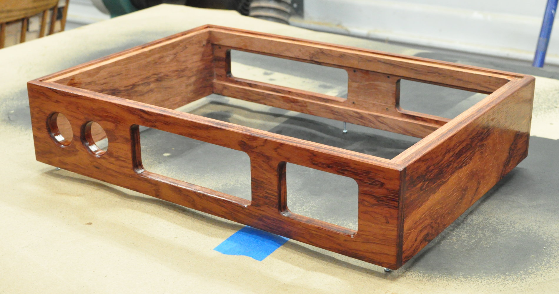
This wood had really striking grain and finishes to a deep rich color. A little wood working and the chassis wood came together nicely. Here’s the chassis fully formed with its first coat of oil finish.
The internal layout was a little more challenging. I needed to keep some things in mind when deciding on the layout. I needed ample separation between the audio signals and the power supplies, I needed to get the tubes all mounted in a manner that still allows changes to take place easily, and I needed to make sure that adequate ventilation was provided for both the vacuum tubes and the main power transformer. Here is the internal layout on which I finally settled.
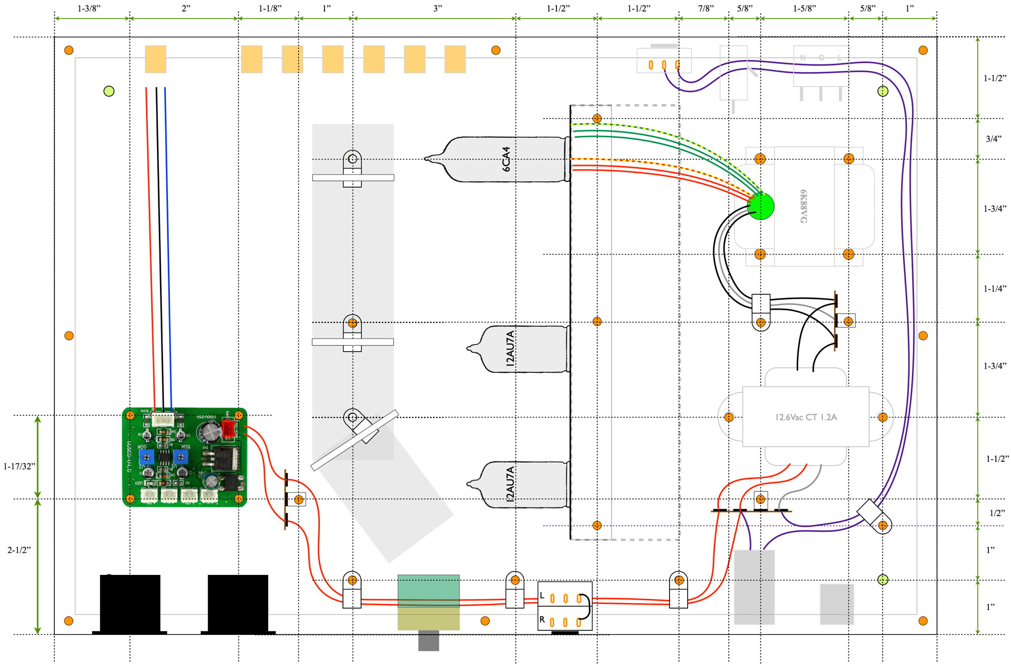
This layout provides the isolation for which I was looking. The vacuum tubes are located in the center of the chassis mounted on a vertical aluminum plate. The AC power wiring is kept as far from the signal lines as possible except for the low current run to the meter board which is twisted pair and run down against the bottom plate. The high voltage preamp wiring is all on the right side of the plate and the signal lines from all the inputs and the meter board or on the left. This layout diagram doesn’t show all the wiring, but it includes enough detail to allow me to proceed with the design.
The layout for the vacuum tube mounting board was fairly straight forward. I ended up mounting a power supply choke on the same side as the tubes. Here is the layout for that unit.
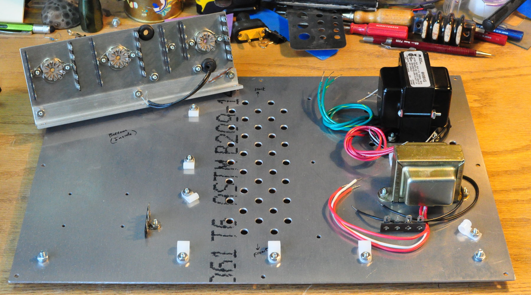
There is a piece of aluminum “L” bracket along the bottom edge which allows the board to be mounted to the base plate. This layout shows the component placement for the power supply filters as well as the buffer and gain stages. Here is how the base plate and the vacuum tube unit look with the basic hardware mounted.
Before I go too much farther I’d like to take a minute to talk about ventilation. Both the vacuum tubes and the Hammond power transformer generate heat which needs to be able to escape. There is not enough heat to require fans or other active cooling, but passive airflow around the tubes and power transformer is important.
Below are the drilling templates for the base plate and the top cover.
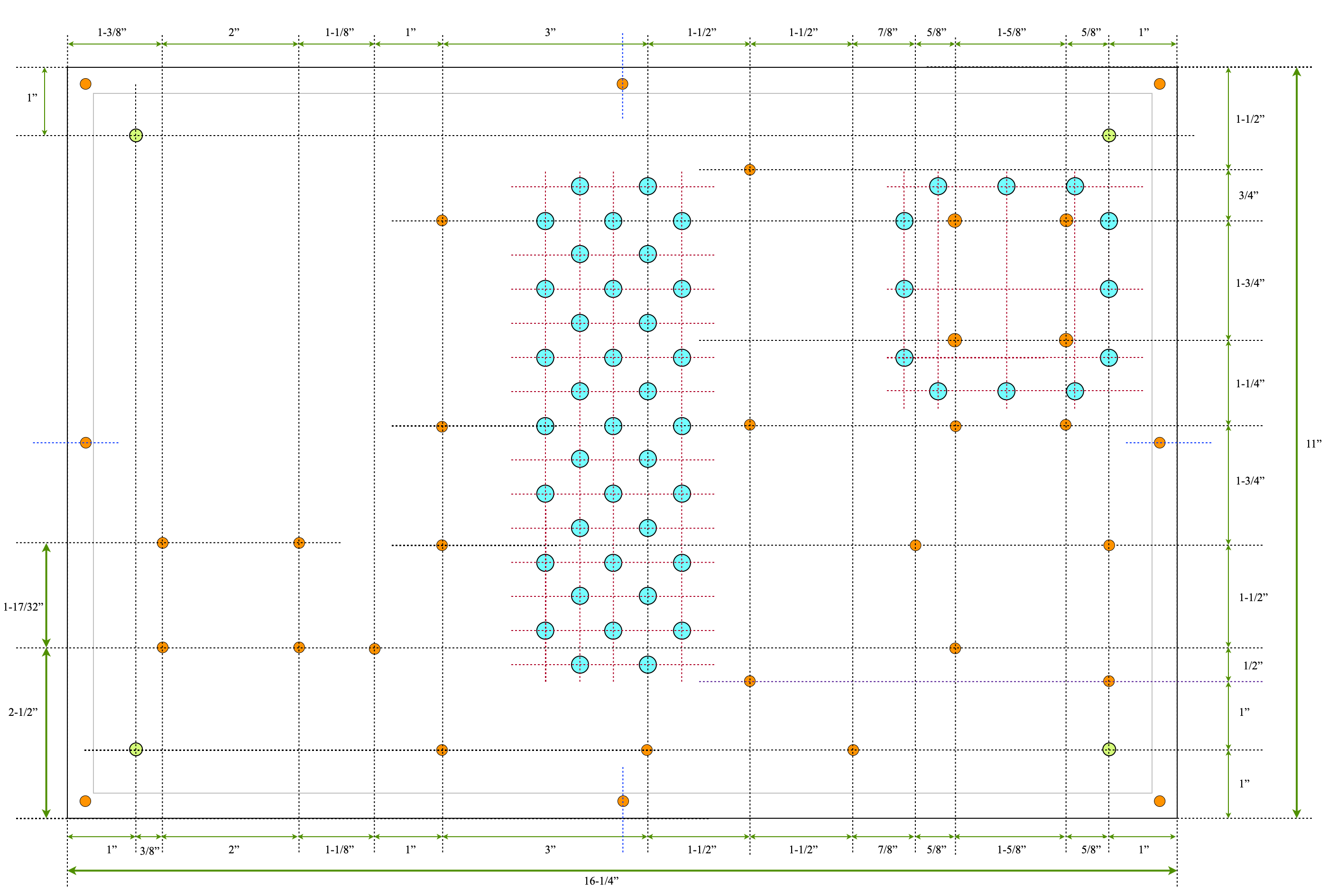
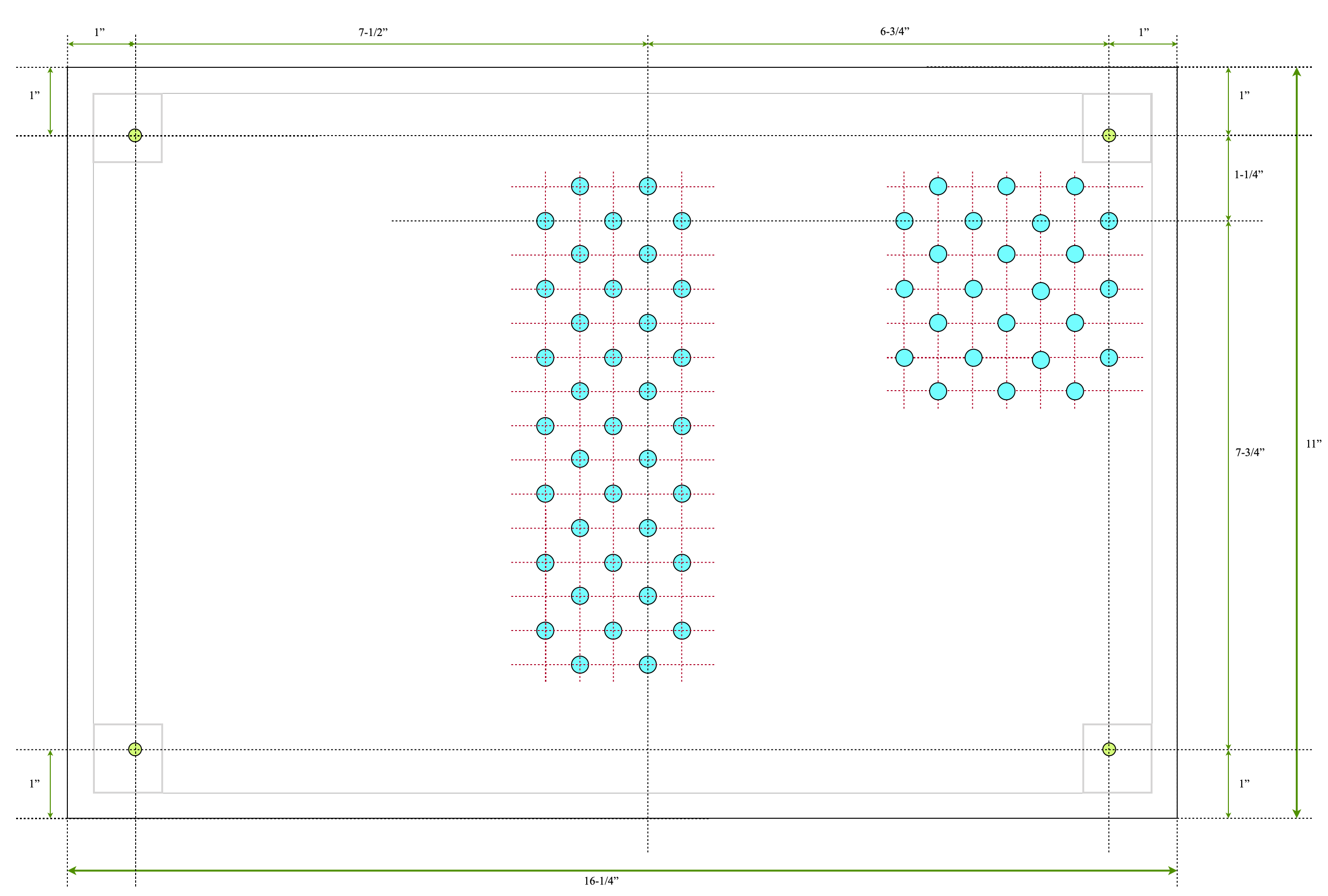
In the base plate there are ventilation hols both under the vacuum tube assembly and around the base of the Hammond power transformer. In the top cover there are matching holes above the vacuum tube assembly and a full grid of ventilation holes above the transformer. The holes are in exact vertical alignment. I did this in an attempt to maximize the passive airflow and keep the inside of the chassis from overheating.
This is how the insides look with the preamp fully assembled.
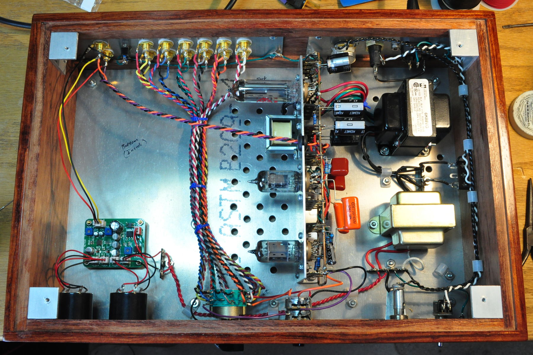
This is actually more open than it looks in the picture. There is lots of room inside for airflow and ample separation between the various signal lies and the AC power leads.
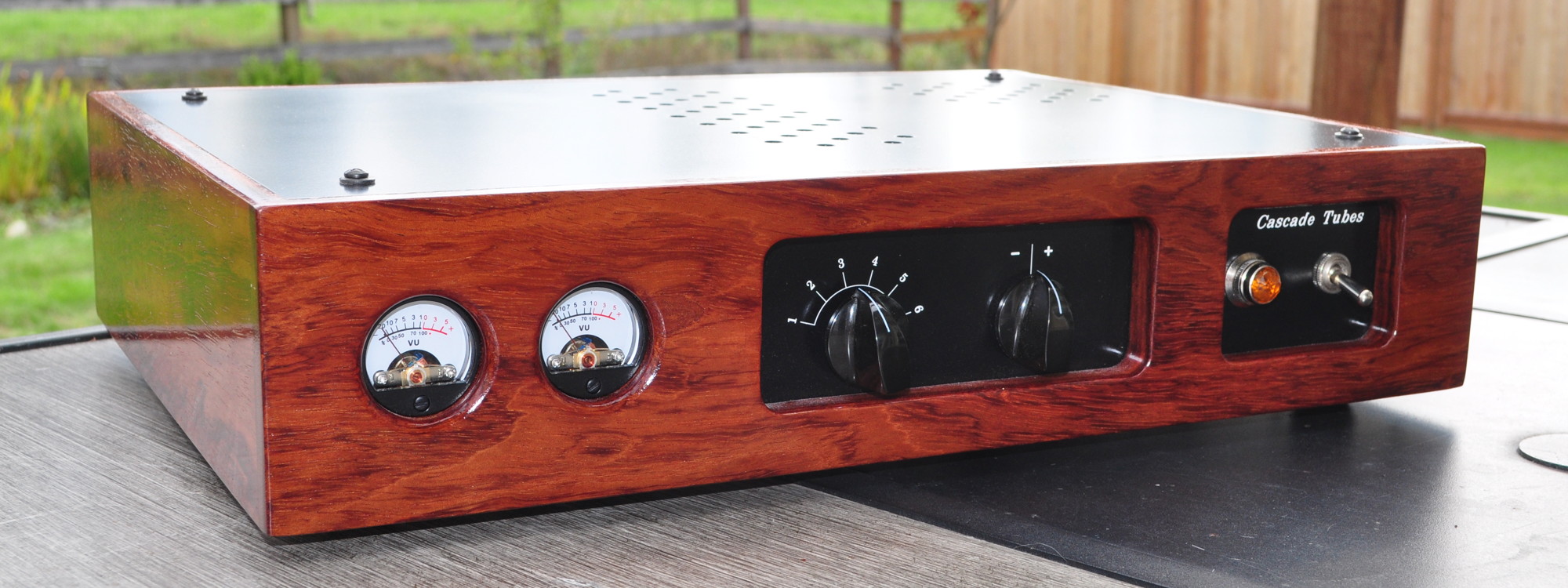
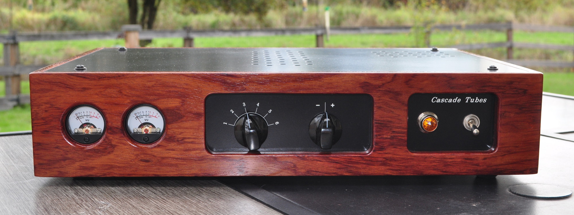
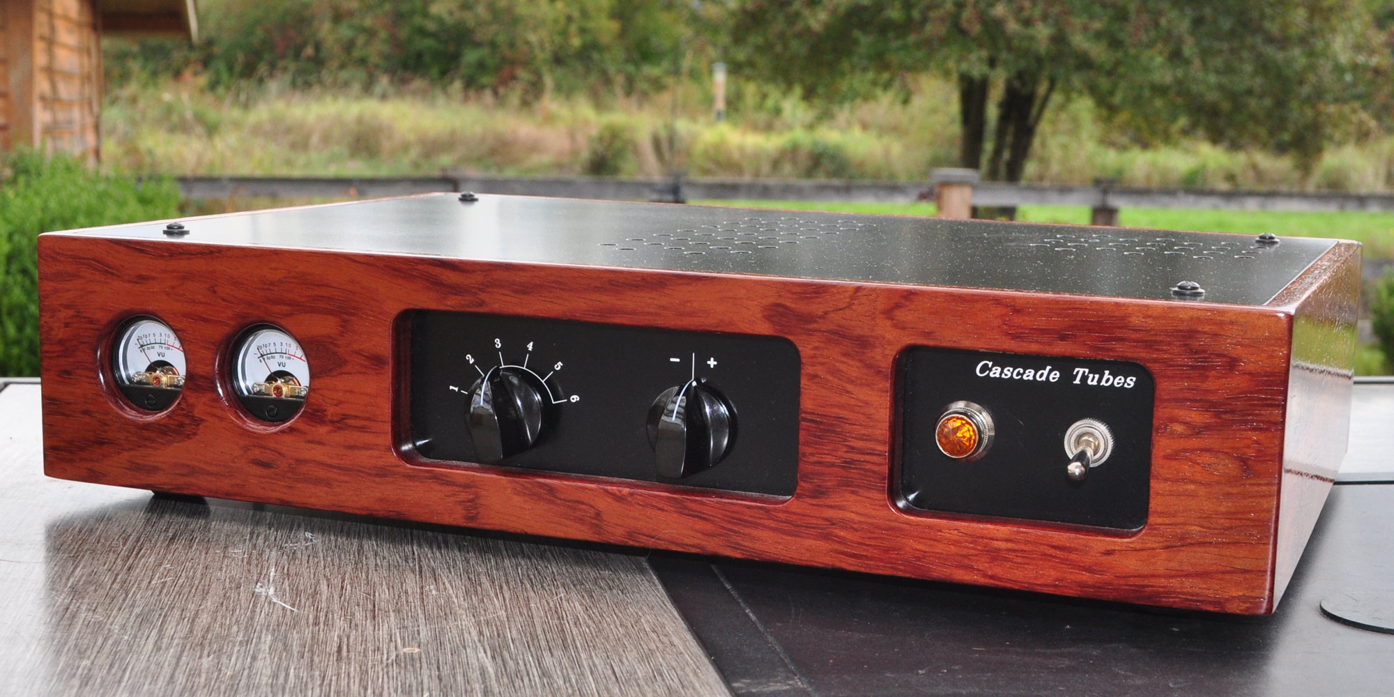
On the front of the unit, from left to right, are the two signal meters showing the signal levels being delivered to the amplifier, there is the six position selector, the level adjustment control, and the power indicator and switch.
Here is a view of the rear of the unit showing the inputs and outputs. This provides a lot of flexibility. The switch between the bank of six inputs and the output terminals is a ground lift switch. I included this just in case one of my various inputs gives me grounding trouble.
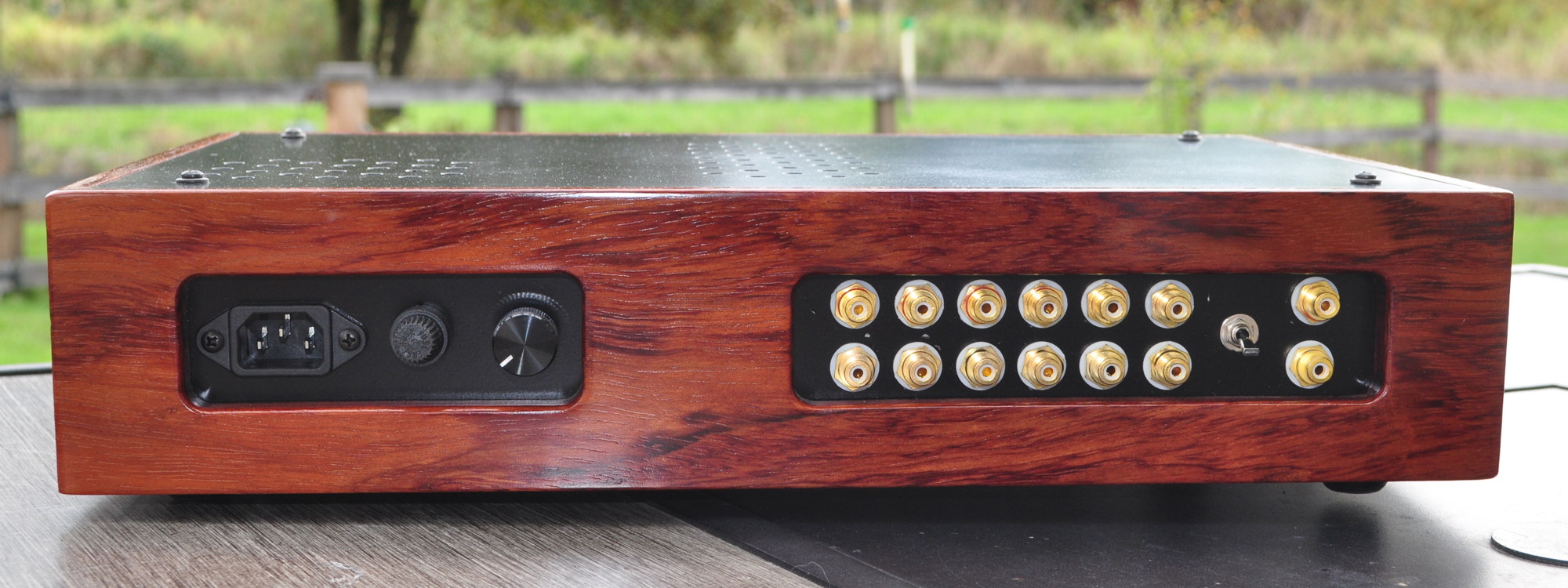
On the subject of grounding and ground lift I should mention the selector approach used in this unit. The selector switch is a 4-pole six position switch. I used a 4-pole switch specifically so that I could isolate all the signal grounds from the various inputs. Only the grounds of the selected inputs are tied to the preamp signal ground. This helps to prevent any ground loops between the SSP and the various sources.
Calibration and Test
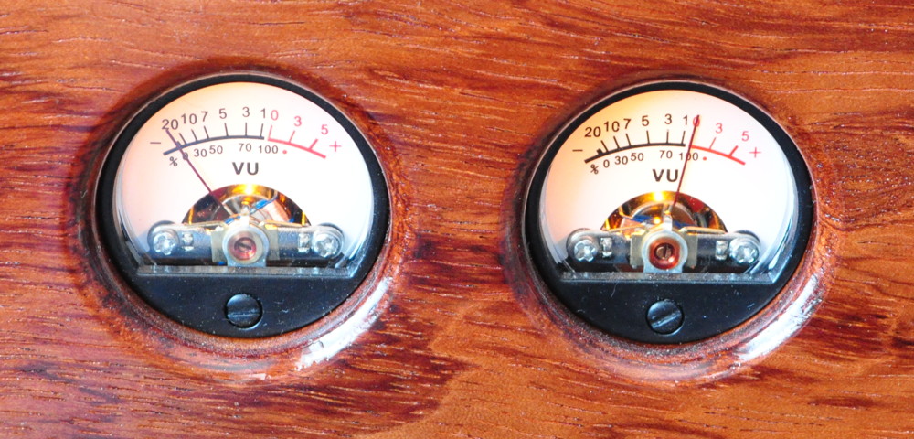
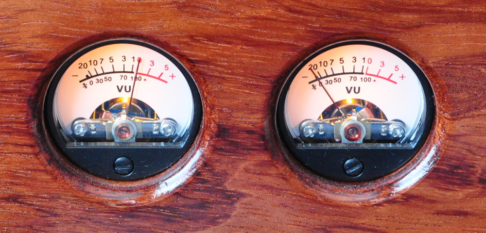
Because this unit has meters to monitor the signal delivered to the amplifier, it obviously had to be calibrated. This was done in the same way the Purpleheart Signal Meters were calibrated except that here the voltage monitoring had to be on the output. I don’t have a picture of my entire test setup but here is the calibration signal and the calibrated meters.
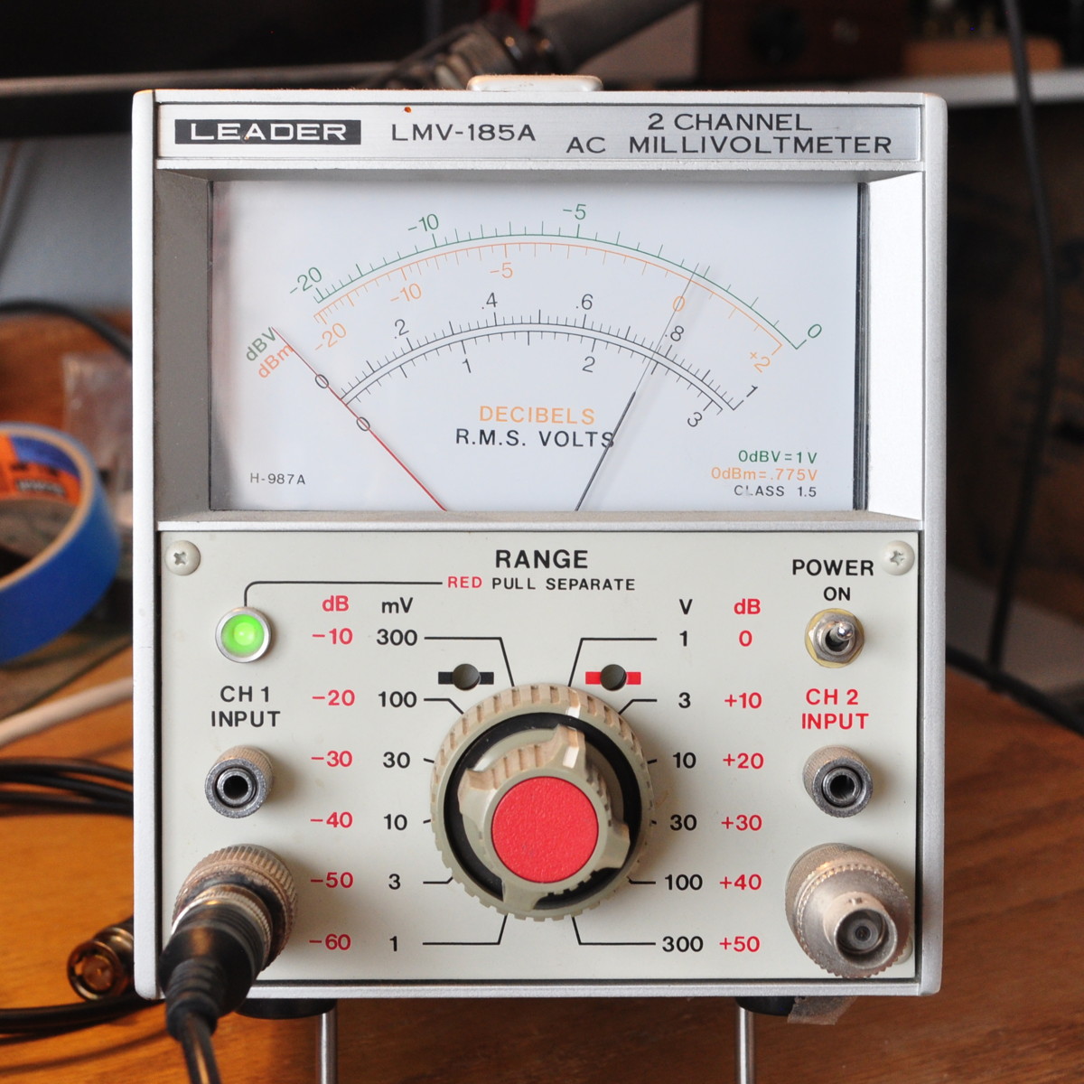
This shows the calibration voltage is set to 0.775v RMS or 0dBu. And here are the calibrated VU meters (right and left).
Once the assembly and calibration were complete, it was time to do some performance testing. But before I started taking measurements, I connected the unit to an amplifier and plugged in an iPod. I’m happy to report it’s dead quiet with no signal, and it sounds really good.
Here are the gain and bandwidth plots from the performance testing.
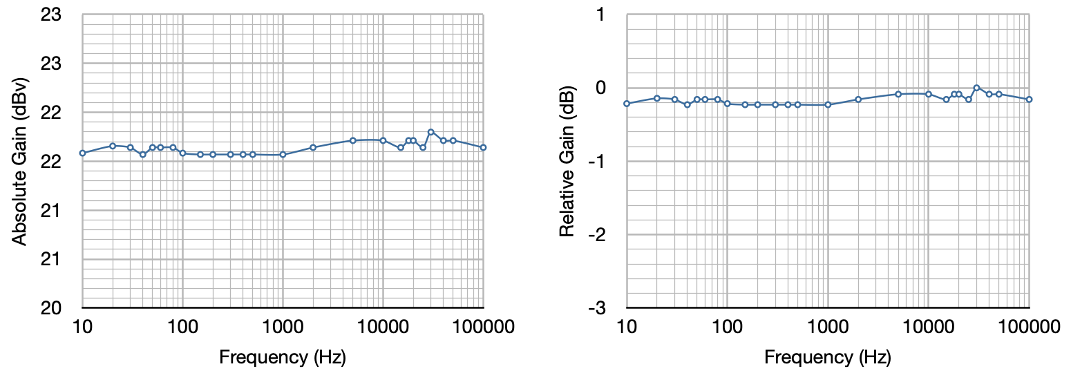
Note that this is the total gain available from the circuit. With the volume control set midway (i.e. at the 12 o’clock position) the end to end gain is close to unity. It also demonstrates that there is lots of control range to adjust line levels as required when changing inputs. The gain variation is less than a quarter dB from 10Hz all the way to 100kHz. This is as designed so that the unit does not contribute to bandpass roll off at either end of the musical spectrum.
Conclusions and Impressions
First, let me say that this unit, when installed in my system, is dead quiet. Regardless of whether I have an open input selected or an active one, there is no audible noise of any type. It also works really well to allow me to swap sources on the fly with minimal fuss. There is ample gain and cut available in the control (i.e 20dB in either direction) to allow me to adjust to virtually any source level.
This Source Selection Preamp is an unqualified success. It is exactly what I wanted and needed for my office system This unit will see daily use for many years to come.
So let me know what you think of the Source Selection Preamp.
Hi Matt,
First of all congratulations on all your projects, really impressive! I have already built the 6V6 Marblewood amp (it sounds amazing!) and now I am planning to go for your source selection preamp. I need, however, a power transformer which has the 230V primary. The closest match to 6K88VG I could find was the Hammond 369JX. Could you please confirm, it would work? On the other hand, I have the impression its outside dimensions are bigger and it will not easily fit inside the box. Would you have any other suggestions?
Thanks!
Witek
The Hammond 396JX is the transformer I would recommend for 230v mains. The internal of the chassis with my design is ≈3.25″ (≈83mm) tall. This assumes that the overall chassis height is 3.5″ (≈89mm) and the top and bottom plate sit in 1/8″ (≈3mm) recesses.
The 6K88VG is approximately 2.7″ (≈68.3mm) tall. However the 369JX is an X6 form factor with a maximum height of 3.06″ (≈77.8mm). This will fit into the chassis as designed with about 0.19″ (≈5mm) to spare. This is close but it shouldn’t be a problem. The transformer is not supplying very much power in this design and the cooling should be more than adequate even with the reduced top clearance.
I hope this helps.
Perfect, thanks a lot!
Could you clarify what Rd is? Would this be selected to obtain the 300V ?
Yes. It is selected to obtain 300V B+ for the gain stages. Although I didn’t mention it on the project page, I did show it in this blog post. I’ll try and remember to update the project page.
Hi matt I just ordered the parts to build this preamp to go with my lacewood amp.I’m having a few problems with the lift switch wiring at the switch can’t see how it hooks up in the photo. Also don’t understand what the three tab tag strip under the rectifer tube is for and where the center taps on the secondary for b+and fillament go do you have any other photos thanks george jobin
Ok. Lets see if I can answer your questions. First the ground lift switch. This switch is a simple switched tie between the signal ground and the chassis ground. Here are two images that should help you see how I wired it in.
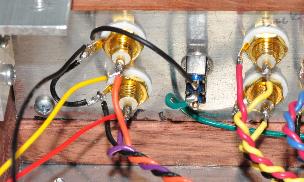 This shows the connection to the signal ground at the preamp output jacks.
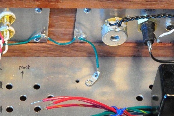
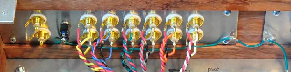 This shows how the switch is connected to the chassis ground jumper between the main power input plate and the plate containing all the RCA jacks. The earth ground on the IEC connector is also tied directly to the main power input plate.
As for the transformer secondary wiring, I have an annotated image.
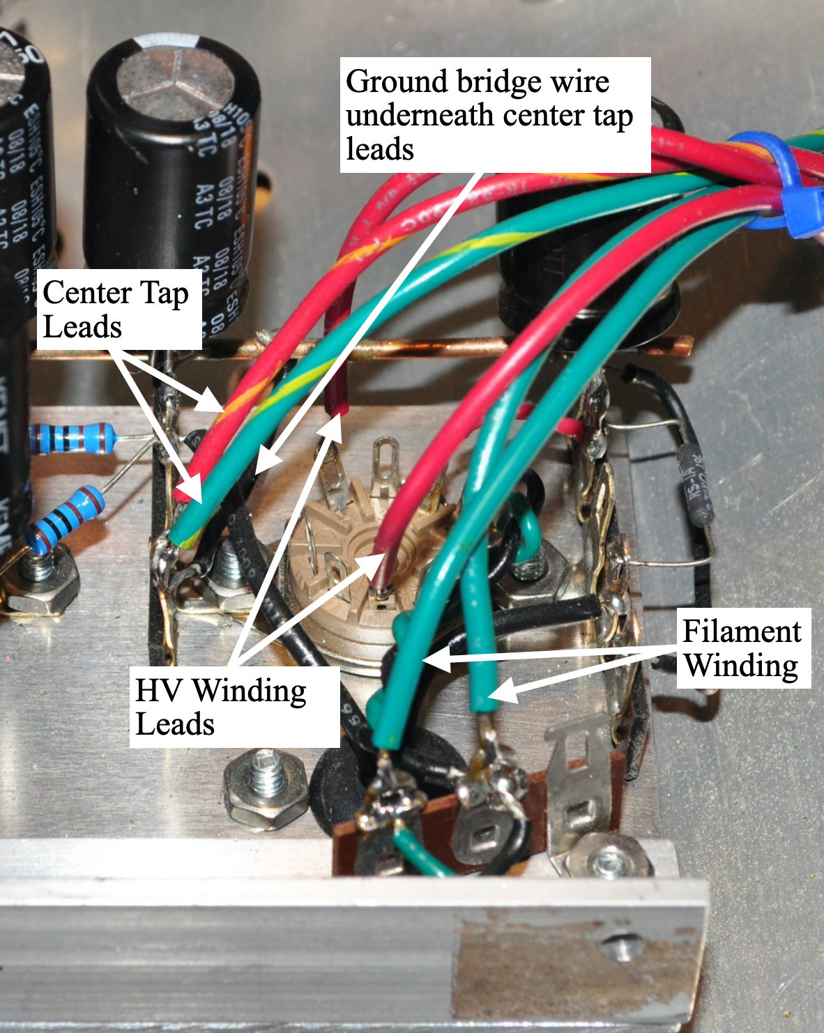
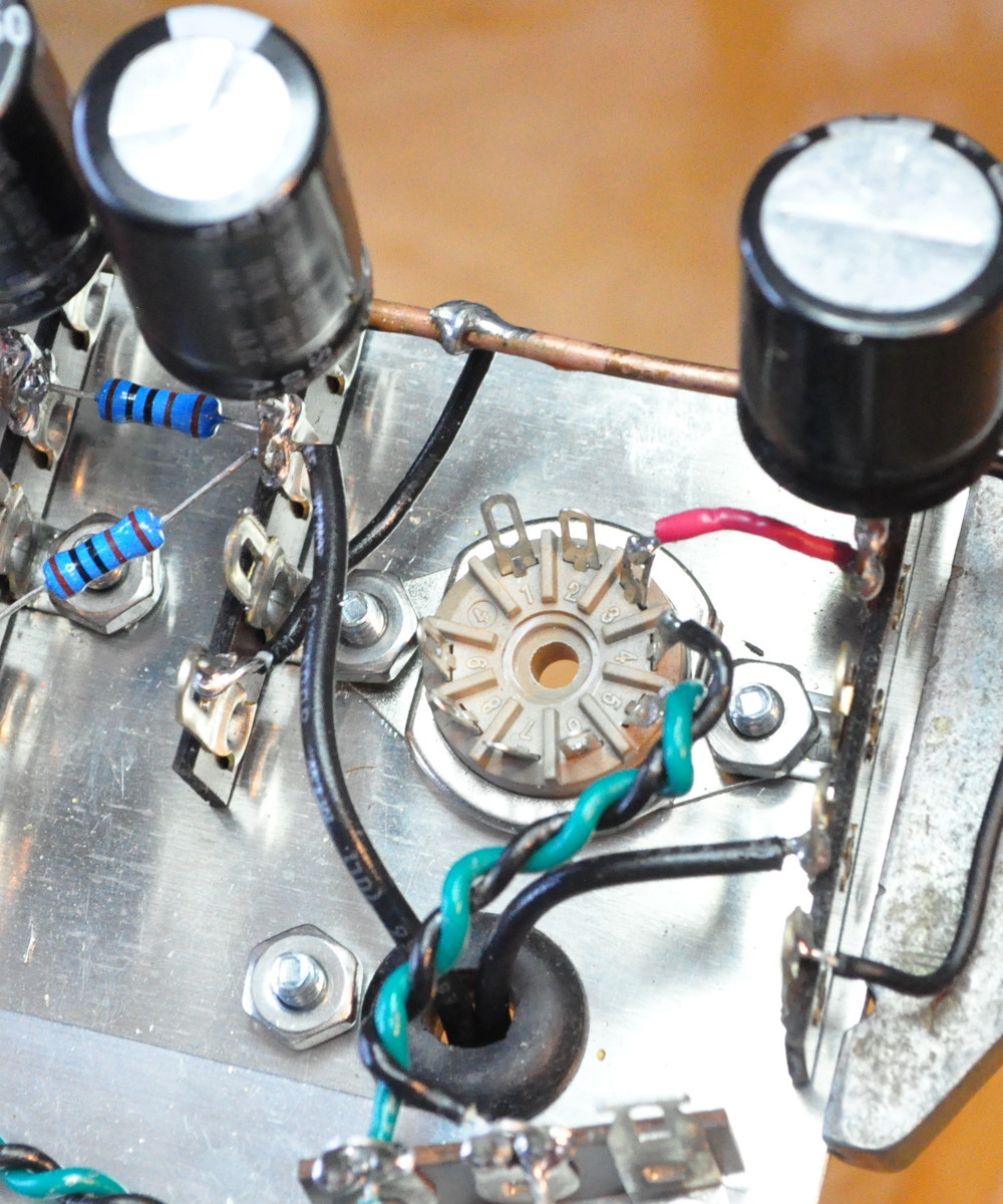
When laying out preamp unit I wanted to make sure that I had simple connection points for all the transformer leads. Here you can see that the three terminal strip at the bottom is a collector for all the filament wiring. The main filament leads connect to this strip. The HV secondary leads connect directly to the rectifier socket. And the center taps for both the HV secondary (red w/ yellow stripe) and the filament secondary (green w/ yellow stripe) connect to the last lug on the terminal strip to the left of the rectifier socket. What is less easy to see is that there is a jumper wire between the signal ground bus at the top and the lug where the secondary center taps are connected. It’s the almost completely hidden black wire in the photo. Here’s an “in process” photo where you can see the jumper wire much more clearly.
I hope this answers your questions.
Thanks matt that clears alot up the only other thing is I have to connect a ground wire from back panel to the last tab where the filament wires then up to the black wire that goes up to the copper ground bus.
I don’t follow. That sounds like you are hard wiring the signal ground to the chassis ground. The third tab on my filament terminal strip is chassis ground. It shouldn’t connect to the signal ground bus except through the ground lift switch.
I see a green wire that goes from the back panel down to either the black wire under the dropping resister or to the ground tab next to the filament wires
Do you mean this wire in this photo with the tab on the end?
This is the chassis ground connection for the entire base plate and preamp assembly. I connected it to the screw that holds the preamp assembly to the base plate. That goes through the hole in the “L” bracket you can see at the bottom of the image with the labels. In that picture the preamp assembly is laying down on the baseplate for access.
That’s it and then at the end of the ground bus there a black wire that goes to the. Bottom lug under the dropping resister it just ends
Ignore the black wire under the dropping resistor. It’s not used for anything.
Ok great and thank you for everything big help
Matt,
A great idea and a beautiful build. I especially like the stencil above the power switch.
Hi Matt,
What is minimum acceptable input POT value? Can I use 100K for that?
Even though I used a 250kΩ potentiometer, a 100kΩ potentiometer will work perfectly well.
A very, very nice looking, and useful piece of equipment. I’ve built quite a few of your amps and have never managed to get the high quality look that you do.
I love the look of exposed tubes and transformers, but this piece of equipment looks fantastic because of it’s sleek design. Looking forward to your next project.
Thanks for taking the time to share everything.