
About a month ago I had an exchange with a reader talking about The Purpleheart Signal Meters and modifying the project to provide multiple inputs and some gain balancing. I’ve been giving this a lot of thought in the last couple of weeks because I have the same needs. So I think this is going to be my next major project.
This project will have some similarities with the Purpleheart Signal Meters but will support more functionality. This functionality will include six sets of inputs for lots of equipment versatility, buffered outputs capable of driving amplifiers with input impedances from the megohm range down to about 10kΩ (i.e. both vacuum tube and solid state amplifiers), a gain balancing control to adjust the selected input signal level to a desired output level, and, of course, signal meters showing the output level.
The physical form of this project will also be a little different from most of my projects. I want to put this unit in my office on the stand with my Cambridge AXC35 CD player. Because of this it will need to “stack” with other audio equipment. This means everything will be internal including power transformers, rectifier tube, gain adjustment tube, and output buffer. The base plate will tie into the wood chassis (as I typically do in my builds) but the top plate will be held in position with machine screws into threaded brackets. This will allow easy access for tube swaps and any other maintenance and trouble shooting.
I have already been playing with some gain and buffer stages. And I think I’ve decided on the rough internal layout as well. An interesting thing about this build is that it will have two power transformers. One Hammond GK88VG for all the tubes and signal circuitry and a separate 12VAC transformer for the signal meter driver board. The reason for this is simple, I already have both transformers on my parts shelf. If feels good to start a project with all the iron already in hand.
For the physical build, I’ve decided to closely match the footprint of my CD player which is the widest piece of equipment I currently have. The final unit (I’m still not sure what to call it) will be 17″ wide, 3-1/2″ tall, and 11-3/4″ deep. Currently the 6V6 “Lacewood” amplifier is sitting on top of the CD player and this project will probably be added to that stack. Probably on the bottom.
While I’m working on the schematic and layouts, I need to find some time to dive into my stack of various hardwoods and fine a nice piece of woof for this chassis. I have some nice pieces of Bloodwood, Wenge, Bubinga, and Padauk I was considering for the 6AS7 “Purpleheart” so maybe I’ll use one of those. However, there are lots of other options in the shop including curly maple, walnut, mahogany, madrona, and apple. This choice may take some thinking.
I’m going to wait for this project as it suits my needs exactly. In the meantime I have the VU meters and control board and want to test them out. I know I can only cut the signal and not boost it but I still want to give it a go. I have the baxandall tone stack and line amp permanently connected in front of the lacewood V.2 in one chassis. If I understand it correctly the tonestack/line amp has no gain. I think I read somewhere that the Lacewood V.2 can accept inputs of around 700mV. Therefore, if I use my signal generator at 1kHz and an amplitude of 700mV and then set the VU meters to 0dB will this work? I have no millivolt meter.
John, If I remember correctly, the tone stack preamp you used was this one.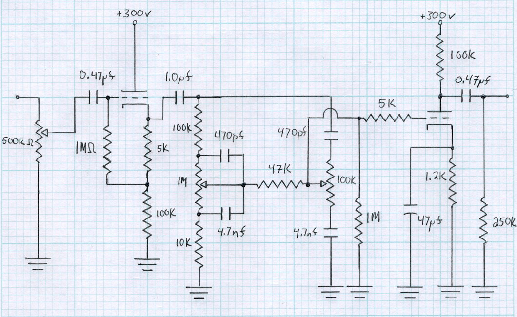 If that’s correct, then the amp has neutral gain with a 12AU7 for the amplifier stage and the volume control set at 50% (12 o’clock). The V2 design reaches full power at about 750mV RMS.
I would not attempt to calibrate the meters in this fashion. 750mV RMS is ≈-2.5dBv or about -0.3dBu. But 0dBu (775mV RMS) is very close to maximum sensitivity of the Lacewood V2. I doubt you could tell the 0.3dB difference in actual usage. I would calibrate the meters to actually register in dBu and that way there are no questions later. This should work out very well in your situation.
Thanks Matt,
Matt, My function generator is peak to peak ( I don’t know if they all are) so I set it to 2.19V at 1000Hz. (I calculate that 2.19V p-p is 775V RMS). With these settings I adjusted the control board trim pots so as to read 0dB on the meters. I don’t have anything to measure millivolts so this was the best I could do. Do you think it’s relatively accurate?
If your signal generator is calibrated then your setting is probably fine. If you have a calibrated multimeter, the normal AC reading should also be pretty accurate as well so long as the frequency is ok for your meter. For example, my Fluke 179 only guarantees AC true RMS voltage readings from 45Hz to 500Hz. So for a multimeter, you may have to adjust your frequency a little.
The thing to keep in mind here is that 1/2 a dB is about a 6% voltage difference. So any voltage from 732mV to 821mV is within 1/2 a dB of true zero. On these scales, that’s very close.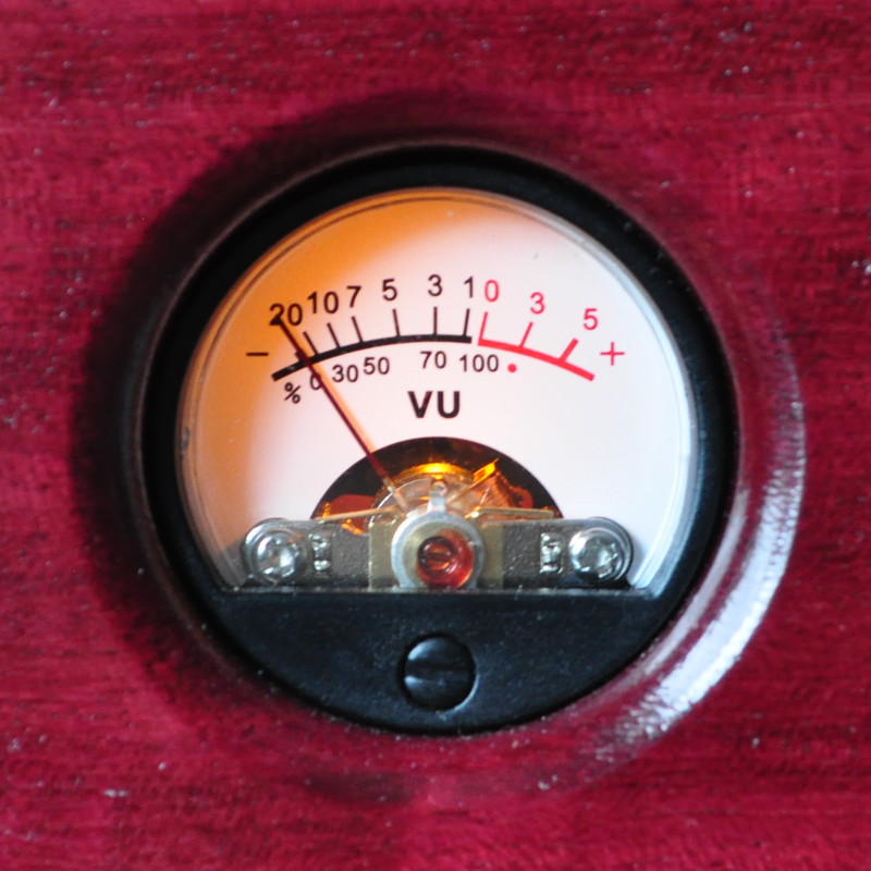 And since these meters are time averaged peak reading, I think you’ll be fine.
You mentioned that these meters are “time averaged peak reading”. I would like to swap them out for two meters I have from a 70’s Nakamichi cassette player. They are marked as dB Peak Level. Would they require a different calibration?
They may. There is no way to know what the driver was for those meters without testing them. I suggest applying some test signals to them and calibrate their response.
WOW! Hawk really jacked up the price on the 6J88VG. When I built my “Color” pre-amp it only cost $16 and change for one.
I was looking around and it seems to be the case across the board. Not just Hawk but all the bigger distributers. In fact, the Hammond 269JX is cheaper almost everywhere. ($0.10 USD difference on the HawkUSA website)
Hi Matt,
I’ve tried everything to find a Hammond GK88VG transformer. No luck. Are they discontinued? Can you give me the Spec so I can find an alternative.
Hawk USA has 150 of the 6K88VG transformers if you want to use them – Dan
The Hammond 6K88VG is one of their industrial line of transformers intended for use by OEMs. I got a couple of these in January of this year for a great deal. Unfortunately, in the last 11 months the price on these units has increased substantially. They are also only available in a 117VAC primary.
Both the Hammond 269JX (115VAC/125VAC primary) and 369JX (universal primary) are an excellent substitute for the 6K88VG. The Edcor XPWR136 is also an excellent replacement. Just be sure to order the correct primary voltage.
Are you planning on including tone controls? I remember a while back you were discussing and presenting a bass and treble control circuit.
The short answer is no. I was considering it but decided that I need to do a little more design work on my tone controls.
The best tone control designs I have right now account for around +/-20dB of boost and cut. This is about a factor of 10X. This is A LOT of variation. I know how to use controls with this much range but they can be tricky when playing with line level signals. Most commercial controls are between +/-6 dB and +/- 12dB. This is a factor of 2X to 4X. It is much more difficult to get into trouble with these ranges. This makes them a better choice for fine tuning the tonal shaping of music.
For designs that I’m putting on my webpage, I have decided that the more restricted range is a better design point. Look for these designs sometime in the near future.