
A Simple Preamp with a Specific Goal
The idea for this preamp has been floating around in my head for almost ten years. Ever since I built and posted about the “Universal” Preamp there has been a lot of discussion about a buffered preamp for adding tube color to lower input impedance solid state amplifiers. This discussion arose because the “Universal” Preamp, with its higher output impedance, is really not well suited for driving solid state amplifiers. So this winter I finally decided to tackle this project.
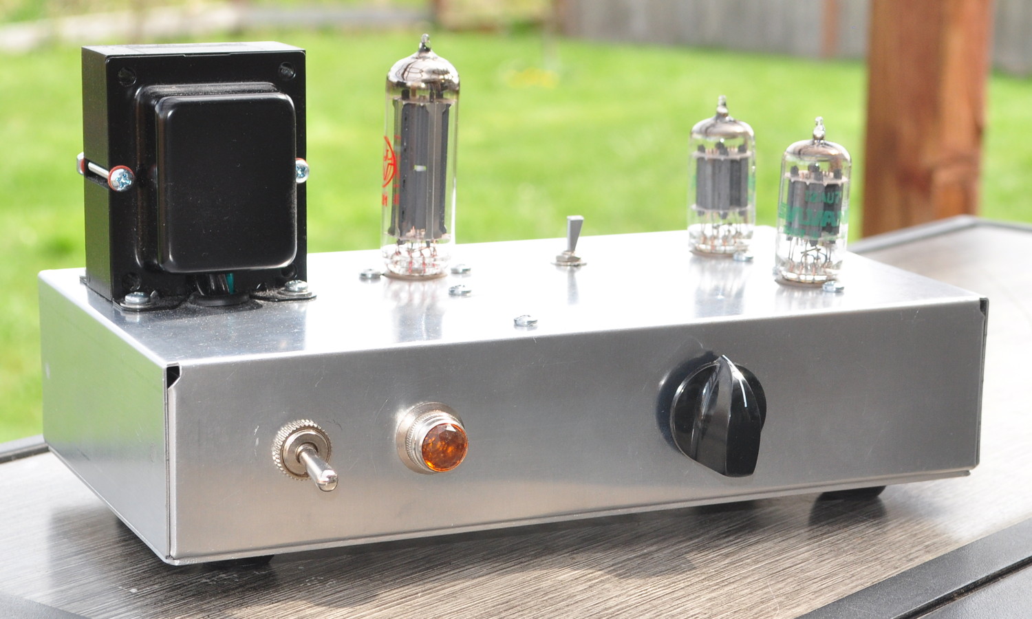
There is an obvious difference between this project and most of the others posted on my website. This project has no nice hardwood chassis and fine finish. Instead it’s built on a stock bare aluminum chassis box. The one I used is a BUD Industries AC-403. The reason for this difference is simple. This project started out as a quick diversion to fill my days while my workshop was too cold to do chassis work for a different amplifier. Too cold in the workshop meant I had to take a different approach. That and, I already had the chassis sitting on my parts shelf.
As it turned out, with components supplier issues, some design mistakes, chassis issues, and a slight rewire, this “quick project” took about four weeks to complete. But the results were excellent. This is a great project for adding just a touch of tube color to solid state amplifiers.
The Electrical Design
For the gain stage it would have been simple to just use the Universal Preamp design.
However, I wanted the ability to provide good gain control (i.e use a lower gain triode like the 12AU7) but provide more color and tonal shaping than the 12AU7 does in the Universal Preamp circuit design. So I went back to the 12AU7 and played with some different loads and bias points. I finally settled on a design which halves the plate load resistance and doubles the cathode bias resistance. To preserve the harmonic character of the preamp, the gain stage is followed by the buffer which is then followed by the volume control. This means there is no attenuation of the color provided by the gain stage at any volume setting.
Here is the final schematic. In this schematic all resistors are 1/2W except the 10kΩ cathode follower load resistor which should be 1W. The final value of Rd at which I arrived is 1kΩ/1W for a final B+ voltage of 297v.
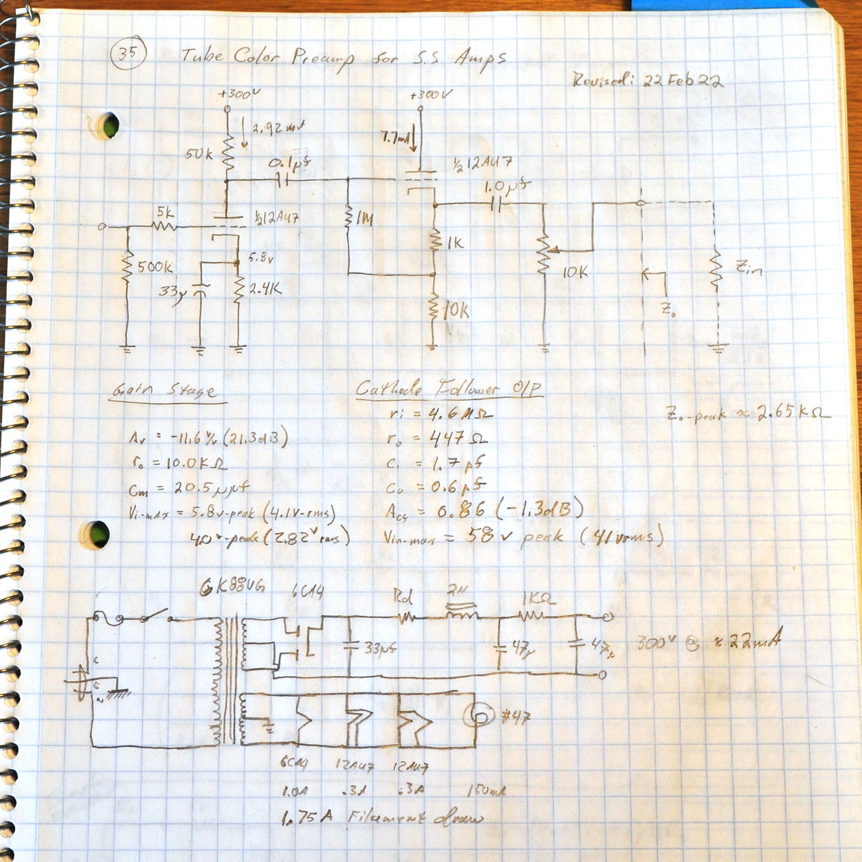
Note that the bias voltage on the gain stage should be 7.0v and not 5.8v. When I changed the B+ to 300v from 250v I recorded most of the changes in my notebook but missed that one.
This design uses an inexpensive Hammond 6K88VG power transformer, a 6CA4 rectifier, two 12AU7s, and just a handful of other components.
This design also has some nice features. Its output impedance is nice and low at all volume settings so it has no problems driving almost any amp with an input impedance above about 10kΩ. The end-to-end gain is just a little under 21dB. So a standard volume control set at 50% (12 o’clock) yields a unity end-to-end gain. As such, if you want to boost your source a little just dial the volume up from half way and if you want a little attenuation, just dial the volume down from half way. The full gain range of this preamp is just about -20dB to +20dB.
The Build
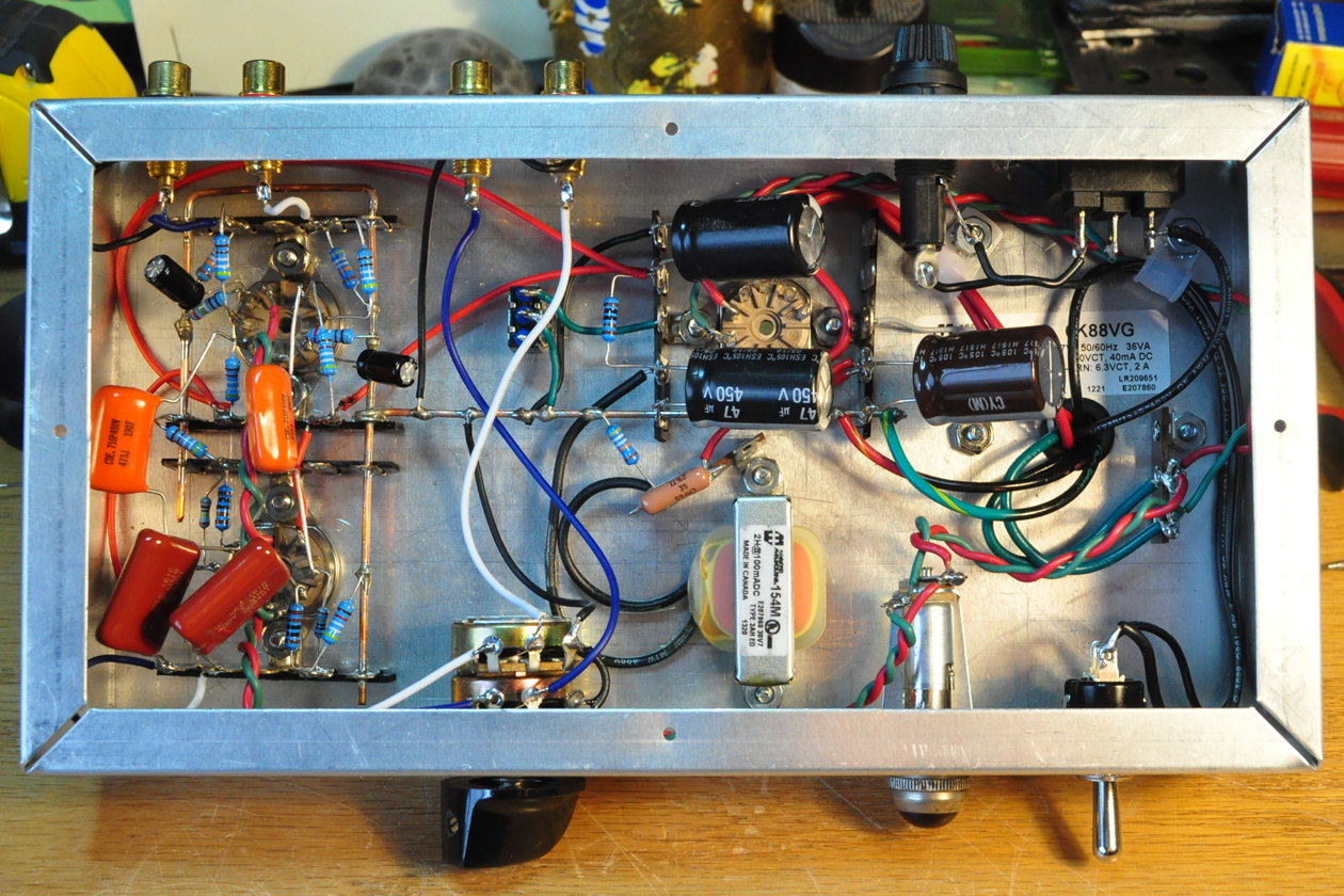
As I said above, this was supposed to be a quick project so the build had to be simple. I chose a BUD AC-403 chassis box from my parts shelf and started layout. This particular box is 9-1/2″ (≈240mm) long by 5″ (≈127mm) wide by 2″ (≈50mm) deep. This provided ample space for all the components even though working inside the chassis was a little challenging. The layout is fairly clean with the power supply on the left (transformer, rectifier, power switch, indicator light, IEC connector, fuse holder) and the audio components on the right (12AU7s, volume control, ground lift, audio inputs and outputs). Here is the chassis box following drilling and clean up.
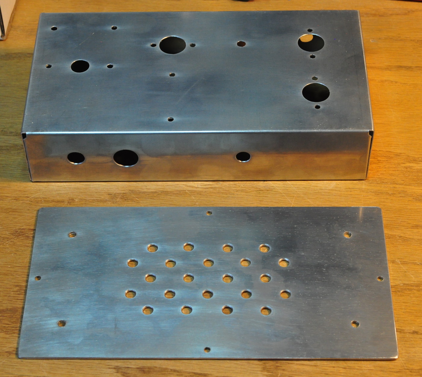
The bottom plate I just made from a sheet of 80 mil (≈2mm) 6061-T6 aluminum. It has ventilation holes and holes for mounting four rubber feet. The hole on the top of the chassis between the rectifier and one of the 12AU7s is for a ground lift switch. This is optional depending on how you wire up your systems.
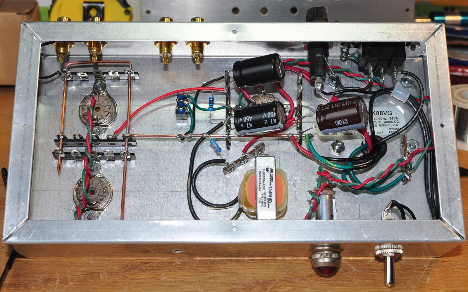
The box provided enough room for layout but I don’t recommend using anything smaller for a chassis. Here is the inside of the chassis with everything mounted to the box (except the volume control) and the power supply wiring complete.
I really wouldn’t have wanted to work in a chassis any smaller than this.
In the above picture you can clearly see my telltale heavy signal ground bus and ubiquitous terminal strips for component mounting. The power supply wiring was fairly straight forward. However, as I moved to the signal side the lack of space began to really make things cramped. Here is the inside of the preamp with everything installed and wired in.
This is a nice layout and the preamp is dead quiet. But it was a challenge sometimes getting my fingers in there to get components installed. Here is a closeup of the gain section wiring in the final preamp.
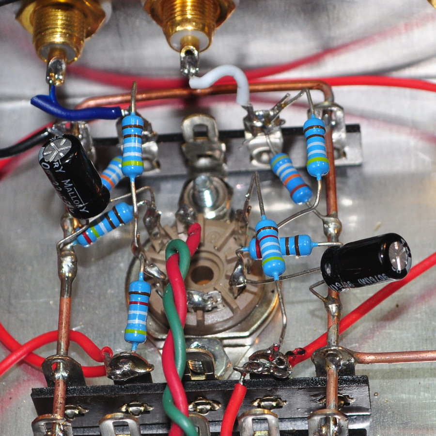
This image really doesn’t do justice to the three dimensional nature of the wiring and components. This is before the coupling capacitors were installed.
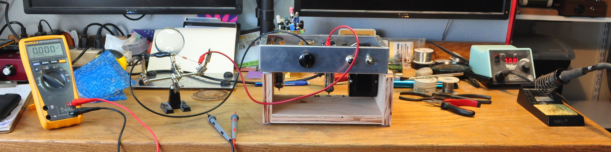
And here is the preamp as I select the final power supply dropping resistor to get the 300v B+ dialed in.
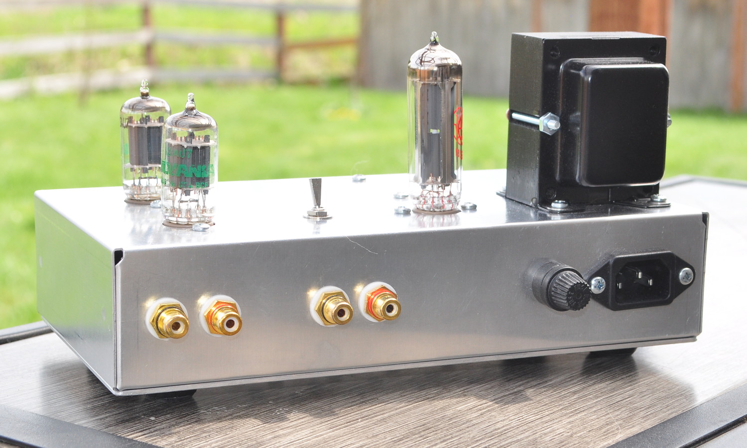
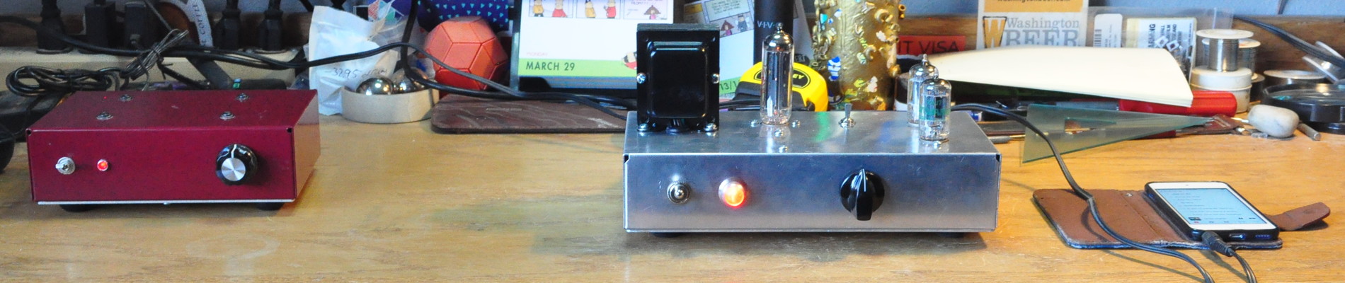
And for anyone curious, here is how the preamp looks from the back showing the signal and power connections.
Testing and Performance
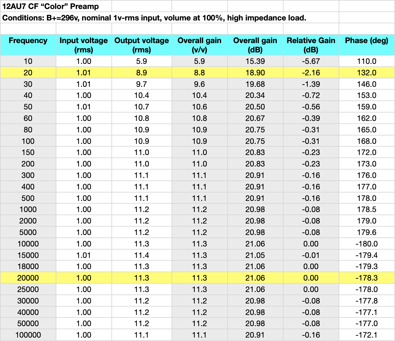
Here are the initial spot checks on both channels. This is with the volume set a maximum.

The gain in both channels is just about 21dB. The max input voltage before the harmonics start to rise is 2.45v-rms or ≈3.5v peak. This is 7.8dBv or 10dBu. At these levels the preamp should be good to go for just about any line level source.
As can be seen in the table, the preamp adds about 1% second harmonic color to the signal. This may not seem like much but it’s just about the right amount to add some nice warmth and depth to the typically sterile class-D amps with which I tested the preamp. Here is the passband gain and phase characteristics.
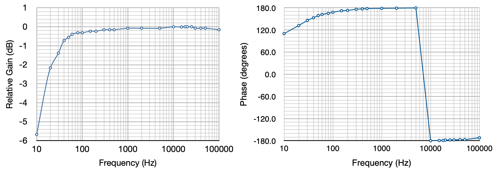
The amp is pretty flat at high frequency up until between 50kHz and 100kHz where Miller capacitance starts to take hold. A nice gentle rolloff at low frequencies is present. The response is down ≈0.7dB at 40Hz, ≈1.4dB at 30Hz, and ≈2.2dB at 20Hz. This is a good and properly controlled response curve. For anyone curious about the values, here is the table with direct measurements and calculations.
The minor variations in the pass band I directly attribute to the LSD values recorded in the table. As I’ve said many times “Real men don’t quibble over tenths of a dB”.
Summary
This started out a simple and quick project just to pass some time. However, the results achieved are really outstanding for something so simple. This preamp is a great way for someone to break into vacuum tube audio without having to abandon their solid state gear.
Hi Matt,
What would be the result and potential problems using this preamp to drive a solid-state amp with an input impedance of 8K?
It should be fine. The buffer was designed to drive a sub-10kΩ load without issue. With the volume control at 50% (neutral gain) the load on the buffer stage with an 8KΩ amplifier would only be 9kΩ+(1kΩ || 8kΩ) so about 9.8kΩ. The color preamp design will handle this with no problems.
Hi Matt, first of all, thanks for sharing this, I am still learning about tube preamps and this helps a lot. Is it possible (and what are the consequences) to use high voltage NPN transistor (MPSA42, for example) emitter follower instead of tube cathode follower? I tried to simulate it in ltspice and it seems to be working well.
I will say that it is possible. However, as they say, The devil is in the details.
The topology of this preamp is based on the preservation of the 12AU7 tonal characteristics. This is why the volume control is on the output rather than the input. So the 12AU7 always sees the full input to the preamp. The consequence is that the output swing of the 12AU7 can be quite high. With a bypassed gain of 21.2dB (-11.45 v/v) an input signal of 3.5v-rms (or ≈5v-peak) (this is a high but not very unusual line level signal) could produce a peak output of almost 57v-peak.
Whatever buffer stage you design MUST be able to handle this magnitude of input swing without overload. And it must be able to meet these swings when loaded with a 10kΩ output control. This is not an insurmountable set of requirements, but it will take some careful design and prototyping to ensure performance. I would NOT trust SPICE for this analysis. Built in limitations makes SPICE unsuitable for large signal analysis. You must prototype.
Is there some reason you don’t want to use the additional 12AU7 for a buffer?
Is it possible to use 316V on B+ or is a little hot for this circuit ?
Yes. 316V is only about 5% high. This is totally acceptable.
Matt:
First – this is a terrific and simple design to add tonal color to the somewhat dry and sterile solid-state amps (and preamps as well!), I saw your design on “Skunkie Designs” where she gave u lots of Kudos. I have been pondering different designs for a tube-based buffer for my Emotiva RMC-1 Atmos processor/preamp to Emotiva Gen3- 7 channel 200W/channel & BasX 5 x 80W/channel amps – these are XLR balanced input/output connections. The system is set up as a 7.3.4 (7 floor/wall mounted Def Tech towers all with internal subs, 3 managed bass channels – 2 in the BP2000TL Front L&R towers controlled via LFE input setup in RMC-1 as dual mono and a Velodyne ULD18 located behind 4 x home theater seats setup as center LFE subwoofer). Subs are self-powered @ approximately 500W each. The rest of the self-powered subs in center, surrounds and rears are speaker line driven set to “large” in processor. The 4 height /ceiling channels powered by the 80W/channel amp are Def Tech BPXs x 4 also set to large given their high wattage rating and full range capability (given the 6 drivers per BPX).
I understand that this 12AU7 based “color” preamp is designed for a line level input relatively fixed input voltage/signal. Question can this be used in between the RMC-1 preamp/processor and the Power Amps to add that tube warmth considering the variable output voltage from the RMC-1 preamp to the Color Preamp input? What is input voltage minimum/maximum operating range of the Color Preamp before 12AU7 is driven past its functional operating range? Is it represented in one of the charts you included above?
I see 2 problems 1) the fiddling with the RMC1 preamp volume and the output volume of the color preamp to get a distortion free level, then if I raise/lower RMC-1 volume within my listening range will I have to fiddle again to balance the 2 preamps? 2) since the master volume of the RMC1 controls all of the channels proportionately depending on how I have each channel level preset by the surround sound level controls (can be set manually or manually using a db meter or automatically using external software, a PC and special microphone designed to adjust each channels level and tonal response with compensation for room dynamics and speaker efficiency/frequency response), I foresee an issue if I chose to add this to only 3 front channels – I would have to run channel equalization with the color preamp installed and without it installed saved as 2 different configurations. More of a concern is the output level range of the RMC-1 may be too wide for the color preamp to perform effectively as it was not designed for this application.
Without going into too much detail my initial thoughts if we were to get this to work, I would build a 2 or 3 channel version with balanced inputs/output and a bypass switched circuit to perform A/B audio comparison test on the Left & Right front channels and the center channel, as these 3 would provide the best example of the tonal changes this device would provide. If successful, I would test the remaining surround channels with the same purpose in mind – is there enough of a difference to build a 7-channel unit.
Ideally, if I could set the color preamp to a fixed output (or if required, by adding an input level control and setting both adjustments) to suit the range of level I use with the RMC-1 without having to fiddle with the color preamp this would be ideal – I would lock in these setting with a run of the automatic level adjustment software with and without the color amp so I can switch as needed or for maintenance as the color preamp would be built with bypass for all channels either by group or individually .
Chris
The maximum input voltage of the Color preamp is 2.45v-rms or ≈3.5v peak. This is 7.8dBv or 10dBu. So long as your preamp doesn’t exceed these levels you should be fine.
In the schematic for the “color preamp” I assumed that one tube would be used for each channel. In your actual build, however, it looks like you used one tube for both inputs and the second tube for both outputs. Is this for better isolation between input and output stages?
Thanks,
John Ramsey
No. It’s just the way I built it. You can allocate the tube elements in either way.
The way I did it helps in identifying a failure (because you can swap the gain and buffer elements independently), but it doesn’t save anything in fixing a problem. You do have to be careful when combining a gain and buffer stage if the heater-to-cathode voltage is too large. But in this design that’s not an issue. However, I do find that gain stages have the lowest noise when the heater is referenced to ground.
Thanks Matt,
I’m going ahead and building it the way you did. I’m currently driving a solid state amp with it, but will later build a tube amp to follow it. I’m thinking of building one utilizing 6BQ5’s in push pull driven by 12AT7’s as in an old Rockola Juke box amp.
Cheers,
JR
It turned out great Matt,
I sang in a quartet in the 70’s and the songs we recorded with tube mics and tube amplifiers and cut to records now sound like I remember them. Thanks for a great little design!
JR
Great! I’m really pleased when projects turn out well. Enjoy your new preamp.
I was searching through the internet on a quest to add tube preamp to my solid state guitar amplifier (Roland JC40). Would this work with some tweaking or is it a bad idea?
The input stage of the RC40 has a gain of about 3.5 (≈11dB) so the nominal gain of the preamp shouldn’t be a problem. The RC40 input impedance is relatively high for both the “low” and “high” inputs. This preamp should drive them fine.
When dealing with guitar amps the input levels are typically much lower than most audio equipment. So the layout for the preamp should make isolation and low noise a priority. The schematic shouldn’t need to chane any but the layout should be made larger to minimize any noise or hum at low levels. Definitely include the ground lift switch so that the signal ground can be referenced to the amplifier and not the mains ground. Otherwise you should be good to go.
Dear Matt, I find this project amazing. I would like to know if using a toroidal transformer as the ANTEK AS-4T500 ( https://www.antekinc.com/as-4t500-400va-500v-transformer ) would have the same results, as the Hammond 6K88VG that seems is no longer in production, the replacements Hammond 269JX are about the same price as the ANTEK toroidal, the toroidal could be hidden under the chassis with I find more aesthetic. I love the sound of the 6SN7 / 6N8P tubes it would be great if a modified version of the 12AU7 design could be done for this, but I don’t have enough background to do so. I don’t mean to be rude, but could you suggest the variations needed for a 6SN7 design?
The short answer on the Antek is that you could probably make it work, but 400VA is massive overkill for this project. This project draws very little power; just a handful of milliamps. If you were using an Antek transformer I would recommend the AS-05TC250 – 50VA 250Vx2 transformer. This is a much better match for this project.
I have not played with the 6SN7 for this purpose. I would have to give is some thought to make sure it works properly with the output buffer.
Dear Matt, thanks for your answer and for the more adequate transformer suggestion. Hope you can find some time to play with the 6SN7. Regards.
Can use 250v b+ instead of 300v b+ any problem
Yes, in a matter of speaking. However, with a B+ below 300Vdc the circuit will not handle the largest input voltages and clipping will result.
This circuit was specifically designed and adjusted for a B+ of 300Vdc to +330Vdc.
I’m having the same issue with only getting about 250vdc from my current power transformer. I built the preamp and it sounds dark. Almost like I have a light blanket over the speakers. I’m also running it into a stereo el84 amplifier. Push/ pull
I am by no means a professional builder. This is just a hobby and with that I used a scrapped power transformers for this build.
I part out old console stereo and stuff like that for my hobby. Keeps the cost down.
And that’s for all the info you’re providing. Very cool
Hi Matt! Really enjoyed reading through this. As someone very new to this – where would you recommend buying the components? I’m hoping you have some sort of affiliate link that might give you a commission, etc.!
Unfortunately I have no affiliates. However, I do have some favorite sources. For most passive components (resistors, capacitors, chokes) I prefer Digikey and Mouser. These are both very reputable suppliers and they have few issues with counterfeit components. For tube related items and some speciality items (like amp jewels) my first choice is Antique Electronic Supply (Yes, I know the name and the web address don’t match). I also sometimes order from Tube Depot and Radio Daze. There is a complete list of tube amp parts suppliers I’ve used on the side bar on my blog page.
I hope this helps.
Hi Matt,
What is the effect on the Spectrum pattern if the 33mfd capacitor bypass on 2.4k is removed? I see it reduces gain, But what about the harmonic spectrum? Thanks in Advance
It reduces the 2nd harmonic and increases the third harmonic with respect to the second harmonic. It makes the spectrum much less favorable for coloring the sound. See these posts: Cathode Bypass and Frequency Range, Cathode Bypass and Frequency Range, Part II, and Distortion Misunderstood for additional information.
Hi Matt, first of all thanks for presenting your wonderful project!
I need more textures and colors in my headphone rig so here I am. Before I have found your project I thought 6922, 6SN7 or 12AU7 are the right tubes for that. I want to make 4 channels cos I want fully balanced in-out and operation. Do you see any problems in that?
I want to use 1 current regulator diode for both cathodes on the input tube. Must I buy a 7mA diode? Sorry but never worked with such devices.
Thank you in advance, if this works out I want donate money for you.
The best way to get balanced operation is with appropriate splitter transformers not just by doubling up circuitry. That actually doesn’t work to produce balanced signals. I would recommend either the Edcor XML series transformers on the input and output or perhaps the Lundahl LL1545A splitter transformer.
I’m confused as to why you want to combine the cathodes of the input tubes. If you use a current “regulator”, be it a CCS or a diode, the “textures and colors” for which you’re looking will be washed out.
Matt, I should have added that I am not using the 147 leslie amp in its tone cabinet. It now repurposed as a decent monoblock amp for simple listing with a horn. I am aware of the 147 limitations as to frequency. That does not bother me. I am looking for its use as a stand alone amp with a full range horn. Thanks for your consideration.
Hi Matt, your design with a 12AU7 tube as a complete pre-amp
Is very interesting as I am looking to mate it with a 147 Leslie amp.
Keeping the Leslie design as is, using the same 10K volume pot interface, are there any issues I should be aware of adding your “color” pre- amp? I added a separate B+ with 10uf and 5 K
Line parallel to the 12AU7 of the Leslie’s phase- inverter, to supply the “ color” 12AU7 pre-amp?
You shouldn’t have any issues. The Color Preamp should drive the Leslie easily.
Two noob questions: I don’t see any circuitry for “floating” the filaments on the cathode follower end, so is it safe to assume that in this instance, the voltage difference is negligible?
Does this have sufficiently low impedance at both ends that it can be well-driven by a low-impedance (computer audio) source into a low impedance solid state line-level receiver input?
Reason for asking is that I cobbled together several attempts at your Universal preamp, taking care to isolate signal and chassis grounds with the proper “star” arrangement, and was happy with the sound quality, but no matter how much shielding, redundant B+ filtering, etc. that I piled on, I could never quite banish the low-level 60hz hum – although it wasn’t as bad with the “ground lift” switch open. Is that an insoluble issue simply on account of impedance mismatch, which this two-stage circuit would solve? Or perhaps it was because my B+ supply was about 40V below recommended max, using silicon diodes instead of the tube rectifier?
Thanks kindly for your feedback. So to speak. 🙂
As for the cathode follower heater, the plate voltage on this cathode follower is approximately 154v. With a B+ of 300v this put the cathode voltage at ≈146v. The limit of the 12AU7 for heater negative with respect to cathode is 200V. So this design contains plenty of safety margin for the tube.
There is no problem driving this design with a low impedance source. I routinely drive mine (and the source selector preamp) with a computer output and a solid state CD player. Neither give me any problems. Driving a high impedance load with a lower impedance source is how you should configure your equipment. Impedance match across the interface is only important in power transfer situations. This is usually only required at RF frequencies to eliminate mismatch (i.e. VSWR) problems.
Without knowing more about your preamp builds I can’t really comment on your hum issue. The prototype shown on this webpage is dead quiet and I routinely use it as a driver when prototyping new power stages. When looking for hum sources it is vitally important to distinguish between mains vs twice mains frequency. The former is a stray field coupling issue and the latter is a B+ filtering issue.
Thanks. I’ll bark up both of those trees and see what falls out.
After reading your comment I will add that the “Universal Preamp” is not well suited for driving a solid state amplifier. That was the reason for the development of this design.
Hi Matt,
is “Color” preamp suited for driving (bi-amping) two amplifiers, one with tubes and oane solid state?
Thank you.
Yes. The channels in the color preamp are completely separate.
If you do this I would recommend that you use independent volume potentiometers, one on each channel. It is unlikely that the different amps will have the same power sensitivity and having separate controls will allow you to balance levels between the two.
Thank you Matt, I would be more interested in the Horizontal biamping, one amp dedicated to all bass L/R and one amp dedicated to all M/T for both L/R.
Hi Matt, I’m keen to build this color pre amp. I have a spare Hammond 369E (230V version of the 269E as I’m in Spain, 230V country). Is there any way I can obtain the 300V CT required from this transformer?
There are a couple of issues. As for the transformer you have two choices. One you can switch to two silicon diodes which will give you about 260 to 265 volts. Then just operate the preamp on the lover voltage and live with the fallout performance. The second is to use the full secondary with a full wave bridge, which will give you around 530v, and use a large dropping resistor to get back down to 300v.
The gain stage should operate ok at 260V B+ with most line level inputs. Only the largest signals may get to the clipping point. The cathode follower is another thing. I increased the B+ to 300v so that I could get the input swing range necessary with low impedance loads. With the lower B+ there is a possibility of overdriving the buffer when it’s loaded by lower impedances.
This buffer design took a lot of finagling to get it to work properly under all conditions of signal level and load impedance. Personally I would not recommend a B+ voltage much below the 300V level.
Thanks Matt.
I only want to add a little warmth to the Lacewood V2. and thought this would be a good way to go about it.
The Universal Pre Amp was the original build I was going to do with this power transformer, but then I read about the extra color available with this design as opposed to the UPA.
I’m never going to want to use it with an SS amp.
Hi Matt
I’ve soldered a power supply for Colour Preamp, and tested it. I’m measuring ~40 VDC when it is switched off.
Should I consider a discharge resistor (say 1MOm 1W) parallel to 33uF capacitor for safety purposes? What would you suggest?
Best Refards
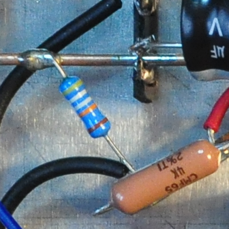
If it’s just the power supply then that’s perfectly normal without a load. Yes you should probably install a small bleeder resistor somewhere in the power supply. I like to install a bleeder resistor on all my power supplies (even though I don’t always show them on the schematics). In the color preamp I used a 499kΩ 1/2W bleeder. At 300v it only draws about 0.6mA and dissipates about 180mW. Here is that resistor.
Thank you!
can i replace 12au7 with 12bh7 on this circuit
Not without redesign. The two stages are designed to work together. The higher µ of the 12BH7 will result in overdrive of the cathode follower and increased distortion.
Thanks for your generosity in sharing this Matt! I just completed my first build ever with your help. A steep learning curve for a mechanical engineer. I added 100k pots on the input and am enjoying playing with the distortion levels.
I’m keen to start another project. Could this design be adapted to 6sn7 tubes with some voltage adjustments?
The implementation is applicable to any triode. I chose the 12AU7 because I was already familiar with it and it’s distortion characteristics. I had also experimented extensively with 12AU7 based buffers.
When you say “adapted to the 6SN7” are you referring to the gain stage or the buffers as well? If you are including the buffer I would have to develop a suitable cathode follower circuit for the 6SN7. Picking a suitable operating point for the 6SN7 should not be difficult.
Thanks Matt. Total newbie so apologies for “quick question, long answer.”
Can you recommend any educational resources for drawing and selecting load lines?
Matt,
Another awesome and very helpful project. It can cost quite a bit of money to get high power needed to drive inefficient speakers utilizing tube builds. This project will allow folks to enjoy tube sound, who don’t have a lot of money for a more expensive tube amplifier build. It is always a pleasure to read you articles and to see your accomplishments.
I think that the indicated cathode voltage of 5.8 V of the first stage is wrong. It probably should be 7 V.
The cathode voltage of 5.8 V would mean that the current is I = V / R = 5.8 / 2K4 = 2.42 mA. That in turn would mean the voltage drop over the plate resistor is V = I x R = 0.00242 x 51K = 123.25 V. So that would give a cathode to plate voltage of 300 – (5.8 + 123.25) = 170.95 V.
But when looking at the curves in the datasheets of the 12AU7 the bias for a current of 2.42 mA at a voltage between cathode and plate of 171 V would have to be about – 8.5 V.
Your schematic indicates 2.92 mA as the current of the first stage. That would give a cathode voltage of 7 V and a cathode to plate voltage of 144 V. When looking at the datasheets of the 12AU7 that would fit.
You are correct that there is some contradiction in what is written in my notebook. And your calculations are roughly correct. The problem is that there are two load lines for this gain stage; one at B+=300V and a second one at B+=250v. This is where the confusion arises. Initially I had thought to use the 250V B+ for this circuit and had recorded that design in my notebook. However, during the design of the buffer stage I decided that I really wanted to increase the B+ for better margin while driving low input impedance amplifiers. When I redid the load line for the gain stage I corrected the numbers in my notebook. It looks like I forgot to change the cathode bias voltage on the gain stage.
Just to avoid any confusion here are the two different load lines for the gain stage. First the B+=300V version.
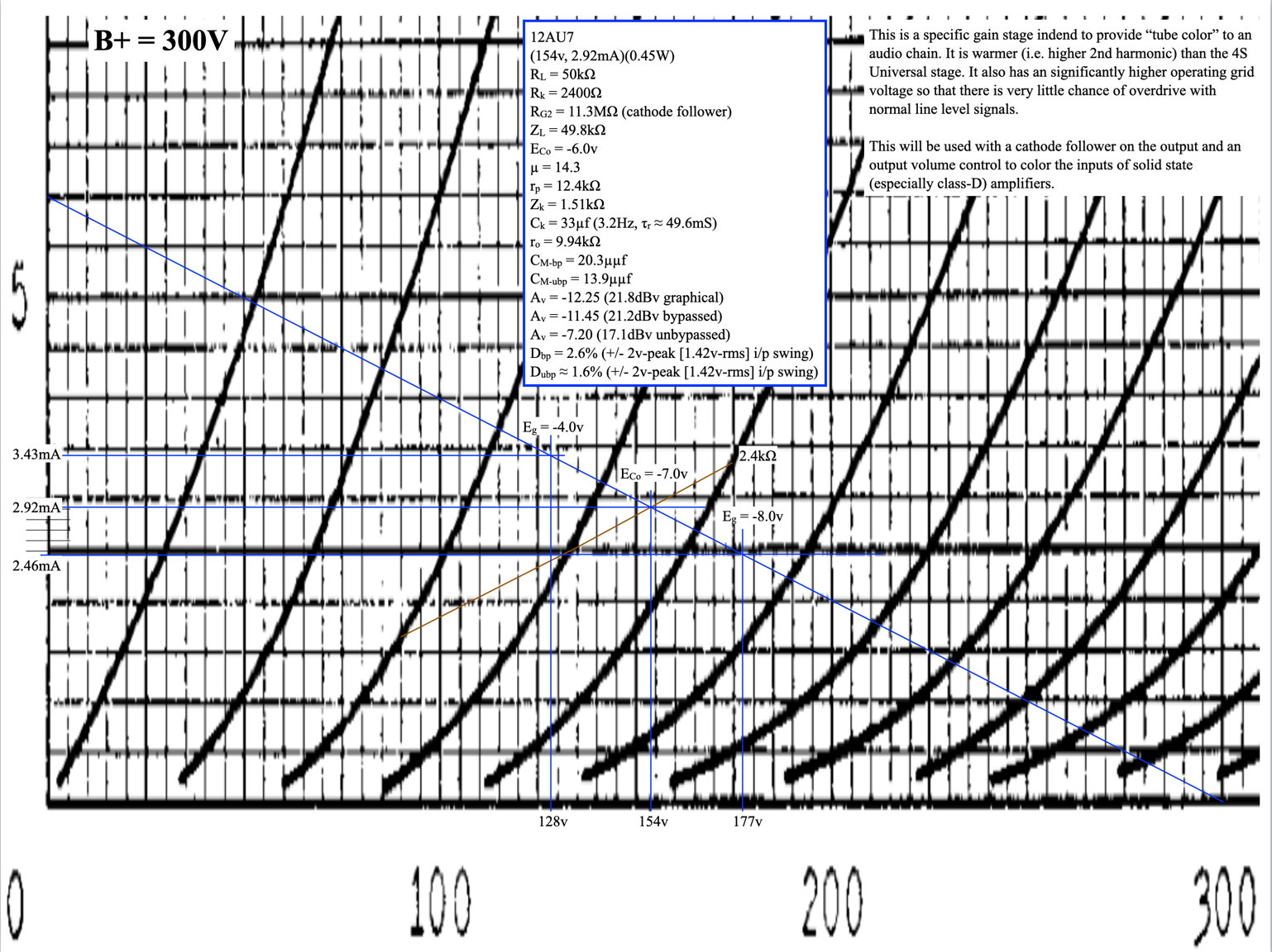 Here you can clearly see the cathode bias is in fact, 7V just as you calculated.
Here is the load line for the 250V B+ voltage.
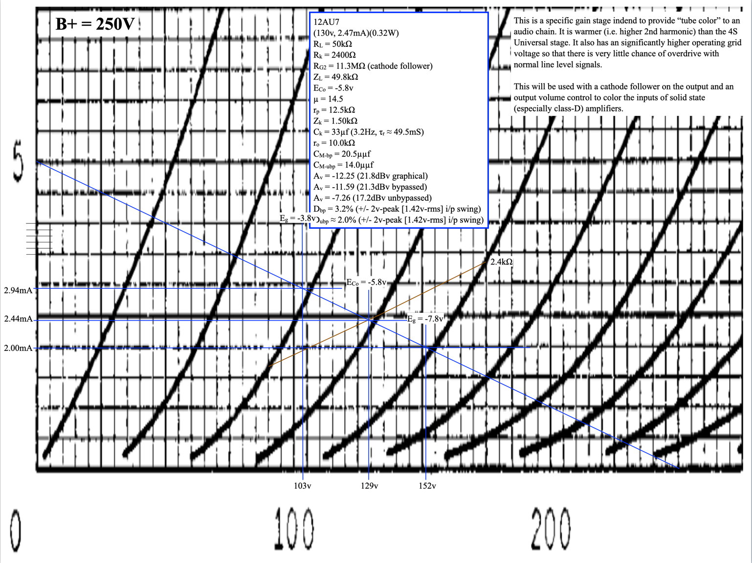 This design is the source of the 5.8v cathode bias number which was still in my notebook when I posted the page.
I hope this clears up the confusion.
Matt, what is that resistor going from signal ground to the junction of the dropping resistor and the choke? I don’t see that on the schematic, but it’s clear on the pictures.
Thanks. Ron Drew
Thats a 499kΩ/0.5W power supply bleeder resistor.
It’s just there to insure that the filter caps are drained when the power is shut off. This is a safety feature for anyone working on the unit. It draws about 6/10ths of a milliamp and dissipates about 2/10ths of a watt when the unit is operating.
Makes sense. Thanks!
Hi Matt,
I am just now building this preamp and have a question. Is the filament center tap going to chassis ground? That’s the way it looks in your pictures, but on the schematic you show it connected to the ground bus. Thanks Matt, and thanks for posting all your designs and builds. They are inspiring.
Both the filament center tap and the HV center tap are connected to the signal ground bus.
For reference, they are labeled in the following picture.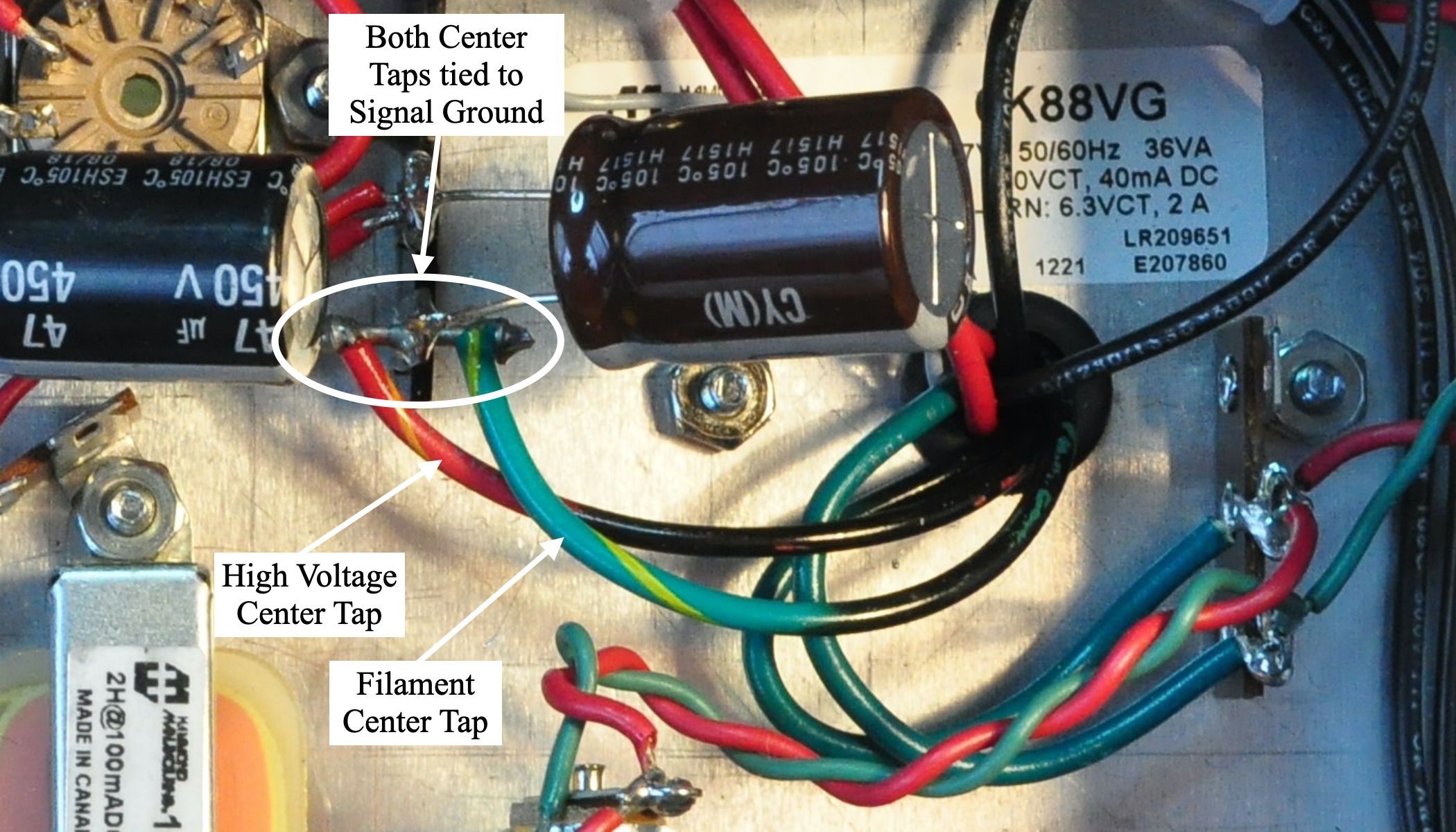
I hope this helps.
Do you know if the EZ81 rectifier tube is known to produce any noise? Not in the music but from the tube itself? When I first completed my build and after a few days of listening one day I noticed a high pitched shimmery sort of sound coming from the preamp (not the speakers). As best as I could tell it was coming from the EZ81. Turning the preamp OFF and back ON again always corrects the problem for a few days and then it returns. I pulled the tube and replaced it with a new JJ EZ81 and all has been well for about a month+ now until the noise returned again this morning. Your thoughts?
The noise is very similar to the noise heard in this video…
https://www.youtube.com/watch?v=9uOx8JXSXWc
Sometimes this can be caused by poor solder joints at the tube socket. You might try reflowing the solder joints on that socket.
I took a magnifying glass to inspect the solder joints and they all looked good. Even so I wicked away the old solder and and re-soldered the wires. Only got to do 2 hours of listening yesterday without the noise returning. We’ll see how a longer listening session goes later today.
There is one other possibility. Is your power supply wired like the one on the web page? Specifically is the first 33µf cap directly across the rectifier and not any larger in value? Just a thought that there may be something driving down your conduction angle and stressing the rectifier tubes.
Couldn’t find a “reply” button to your most recent post so I hope this response posts correctly.
The PS caps are of the specified values. The first filter cap is on a terminal strip as in your photos. I essentially used the same layout as yours.
Yesterday’s listening session couldn’t have gone any better. Several hours of listening and no noise was heard all day. I’ll give it a few more days to see how it goes.
Well the noise from the rectifier tube returned yesterday evening for the first time since I last posted. FWIW it wasn’t quite as loud as it has been previously. Instead of turning the preamp OFF to reset I instead gave the tube a flick of my finger. Surprisingly this stopped the noise and it didn’t return for the rest of the evening. We’ll see how it goes today.
So far the NOS Amperex EZ81 I’m using has been dead quiet. Maybe JJ has some QC issues. In the past few months I’ve had a JJ 5Y3 that arrived DOA and these two JJ EZ81’s (bought a few months apart) that made the same noise.
This could be the case. Inspect the internal construction of the tubes and see if there are any things that set the new JJs apart from others. I ran into an old 6CA4 that was branded “Matsushita” which had significantly different internal construction from any other 6CA4 I’d ever seen.
I have an ElectroHarmonics 5AU4 that buzzes after a few minutes of operation in every amp in which I’ve ever tried it. Some tubes are just like that.
Noisy tubes, like noisy transformers, happen sometimes. There is not enough load on the rectifier tube in this project to cause any problems. I would suggest just swapping tubes.
Do you have a BOM for the preamp?
Not currently. This was a quick project that mostly came from my parts shelf. I’ll see if I can put one together.
Here is a BOM in PDF format.
Link: https://www.cascadetubes.com/wp/wp-content/uploads/2022/11/12AU7-CF-Parts-List.pdf
This does not include the chassis. Personally I used a BUD Industries AC-403 with a custom made bottom plate. After building this preamp in this BUD chassis, I recommend something a little larger for ease of assembly and test.
One small error. The 10kΩ load resistor in the cathode followers should be a 1W and not a 1/2W.
There’s no attachment for the Bom.
Just download the linked file above.
Dear Matt, could you please attacj BoM. The link you’re referring to isn’t working…
Tnank you!
I have added an HTML link directly under the BOM listed in the comments.
People should be able to download directly from the image link. Download image should grab the PDF file. The link goes directly to the file.
Hi Matt
Approximately how much DC voltage is present on the cathode of the CF output stage (with 300-v B+)? I ask because I have some 1 uf Soviet K40Y-9 capacitors that I’d like to use in this build, but they are only rated at 200 volts. Seems like they would be adequate, but I just want to be sure.
Thanks,
Jim
The CF load line puts the plate voltage at about 215v. So the DC voltage at the cathode should be in the neighborhood of 85v (i.e. 300v – 215v). There should be no spiking of this level at start up or shut down so I think you should be ok using the capacitors with a 200V DC rating.
Thanks Matt
What is the value of resistor Rd in the PS schematic?
I finally ended up with a 1kΩ 2W resistor. I talk about it in this blog post: Not Quite Done
I hope this helps.
Thank you for your reply Matt. Would you mind posting an updated circuit schematic of the preamp & PS with all the final component values shown? I am red/green color blind and am having difficulties determining the new value for the buffer load resistor for one example. Many thanks!
The schematic on the project page is the final schematic. All the values shown are the final values. I have also added a note above the schematic about the 10kΩ buffer load resistor and the value of Rd.
Let me know if you have any other questions.
Matt,
I’ve built the 12AU7 Color Pre to specs and got the following initial voltage readings from the power supply. C1 @ 354V, C2 @ 348V and C3 @ 342V. Is that too much on the high side of 300V? I’m still new to tube circuits so I’d appreciate any guidance you can offer if lowering B+ is in order.
TIA!
Steve
342v for B+ is a little hot for this circuit. Did you include Rd in your power supply? And if so, what value?
Since the current at the target bias point is 22mA, I would suggest (342v-300v)/22mA ≈ 2kΩ of additional resistance for Rd. 2kΩ @ 22mA is about 1W. I’d probably use a 2W resistor just to be safe.
Your voltages don’t make sense to me. There is a 1kΩ resistor between C2 and c3 (i.e. the two 47µf capacitors) and a 6V difference implies only a 6mA current draw. The total draw on the power supply should be ≈22mA with two channels. Have you checked circuit voltages? Check the bias voltages on the gain and CF stages. The gain bias (cathode to ground) should be in the neighborhood of 6V. The cathode follower bias point (i.e. the voltage between the cathode and ground) should be ≈85v.
Thanks for taking the time to reply Matt. I found an error in my connections. Correcting it dropped B+ down to 293V.
Great! Let me know how you like the preamp.
I am totally digging the preamp Matt. I did a lot of going back and forth with and without the 33uf cap in the circuit. Just as before with my 4S Uni-Preamp build I’ve decided to omit the cap. To my ears it just sounds better without it. Thanks again for your assistance.
Steve
Thanks Matt. Can we follow the universal tube swap with this design ?
Unfortunately no. This circuit is purposed designed for the 12AU7 in both the gain stage and the buffer stage. Putting a higher gain tube in the gain stage will lead to all sorts of overdrive and operation problems.
Cool, thanks.
Thanks Matt!
Hi Matt,
Can I try this schematic with 6sn7? Also, can I add. A 100k pot in the input? And keep the 10k output as a Gain control potentiometer? Reason to include 100k being I can’t find motorized version potentiometer in 10 k value..
Thanks
Vijay
The 6SN7 will not work for the buffer circuit without redesign. For the gain stage, you could use a 6SN7 with the same plate load and by reducing the cathode bias resistor to ≈1.8kΩ.
The addition of the 100kΩ pot on the input is a different question. This circuit is designed to provide tonal shaping to the signal. In common cathode triode stages, the 2nd harmonic distortion is roughly proportional to the drive level. By attenuating the input signal you’ll be reducing the level of tonal shaping. This circuit is not designed for a level control on the input.
Matt. Have you tried feeding this to a tube amp yet? Just to see how it goes?
I am pondering this CF modification to my 4S preamp (thank you for that) to expand its utility among my listening setups. Seems good to have a cute little tube preamp that can feed any of my amps — either tube or SS. The 4S design is solid and elegant simple. A CF mod would be easy to do…and shouldn’t be an issue feeding low imp. source to a tube amp, and obviously it’s good for the SS units.
Yes I have. As a matter of fact, here is this little preamp feeding the 6AS7 SET and signal meters.
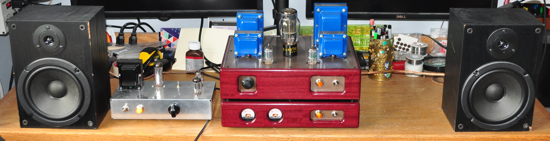 I don’t usually do this as it’s really not required but it works fine. In the image above you’ll notice that the preamp is set for approximately unity gain. However it also does signal boost and cut just as well.
That looks great. I measured and I have room to make the CF modification to my unit. My next project.
Quick question: are those 1 watt resistors off the cathodes of the CF tube? Necessary?
The 1KΩ connected to the cathode is a 1/2W resistor. This resistor only dissipates about 59mW.
The 10kΩ resistor to ground is the more important one to watch. Note that the picture above still shows the 50kΩ resistor in that position. I subsequently reduced this resistor to 10kΩ as I related in this post. Technically this resistor dissipates about 590mW; however I used a 1/2W resistor in this position. I can get away with this because I have tied one end of the resistor to the heavy copper ground bus and the other end to a heavy solder tab. These both serve as heat sinks for the resistor allowing the extra 90mW of heat (in excess to the specification) a path to exit. Technically these should have probably been 1W resistors but I didn’t have any available at the time and I really didn’t want to wait ANOTHER week for a new component. These resistors do not get overly warm in this application.
For others building this preamp, I recommend using a 1W rated resistor in the 10kΩ position.