
So I decided today that I really needed to close the book on the color preamp. This means that I couldn’t just prototype a new buffer and leave it at that. The preamp needed an end-to-end test in it’s final design configuration. So that’s what I did. The results were even better than before.
So if I were going to make this happen, I needed to open up the preamp and make some changes. The buffer load resistors would need to change and the -6dB pad I put on the input would have to come out. Also, the volume knob needed to be realigned. So here are the hardware changes I made in the chassis. First, came the new buffer load resistors.
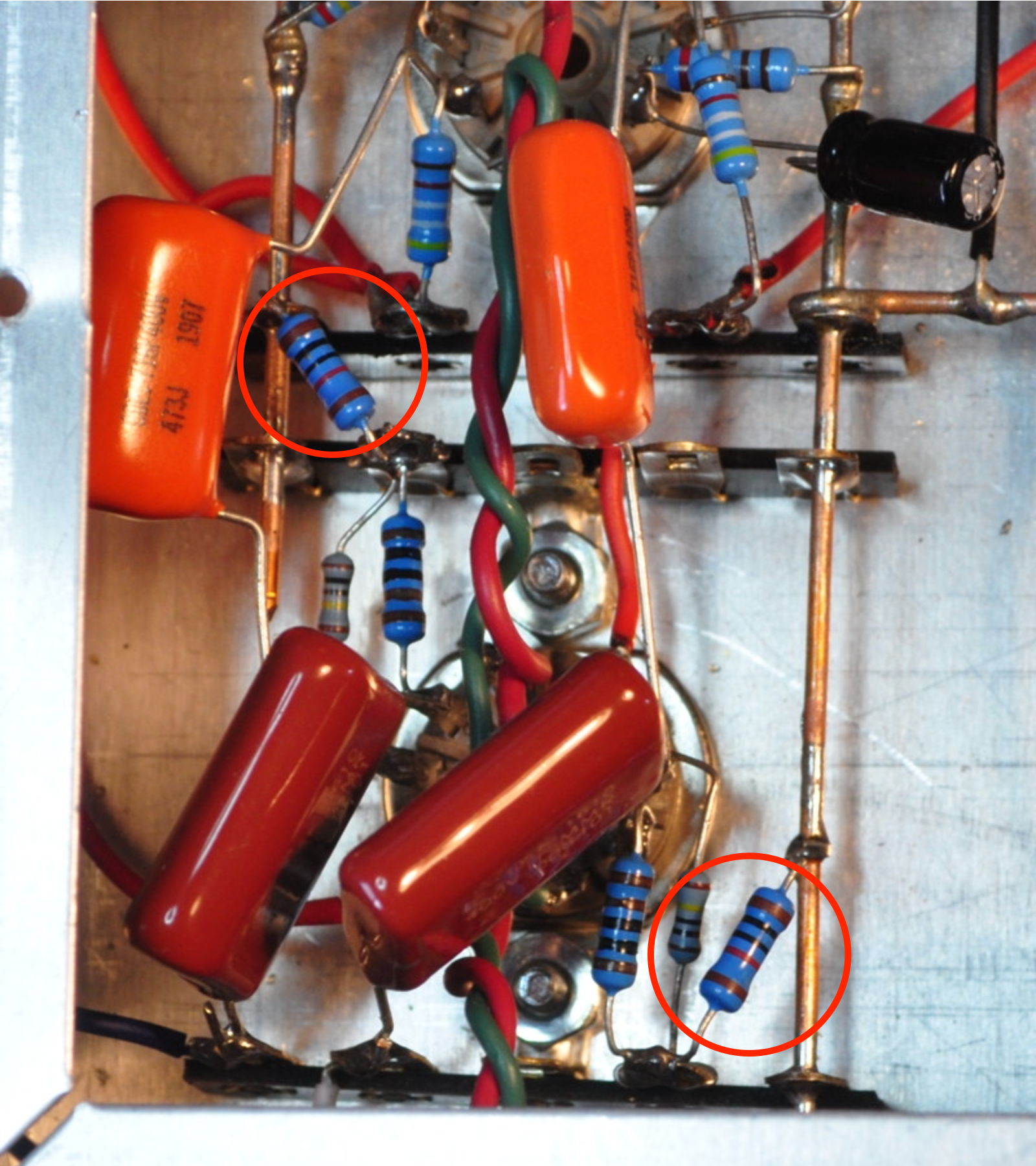
You can see them here circled in red. Working in this chassis was still not easy. Those really are some cramped spaces for soldering in new parts. The other major change was the removal of the pads in the input connection.
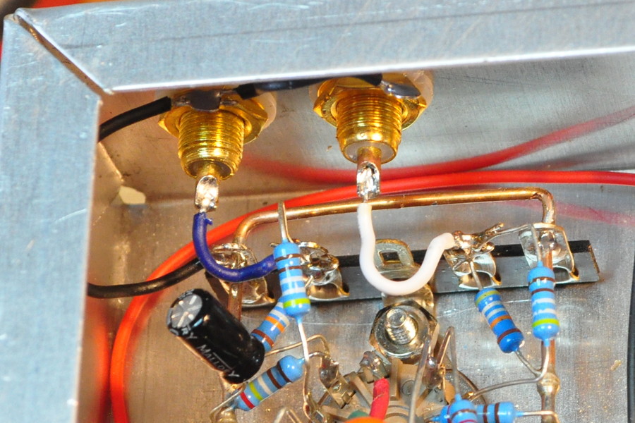
In this picture you can see the resistors removed and the input wires back in place. It was good to get the pad out of the circuit. The additional 500kΩ in the signal line seriously hindered the high end response. With those resistors gone, the original gain stage bandpass performance has returned.
One change which I made on the schematic but did not implement in the prototype was new coupling capacitors. On the revised schematic I increased these capacitors to 0.1µf because I wanted a little better low end performance. But the change is only about 1dB at 20Hz so I decided to leave the 0.047µf coupling capacitors in place. It’s always best to change as few things at a time as possible and I really wanted to assess the new buffer performance.
As before I did a quick spot check at three drive voltage conditions at a frequency of nominally 1kHz. Here are the results for both channels.
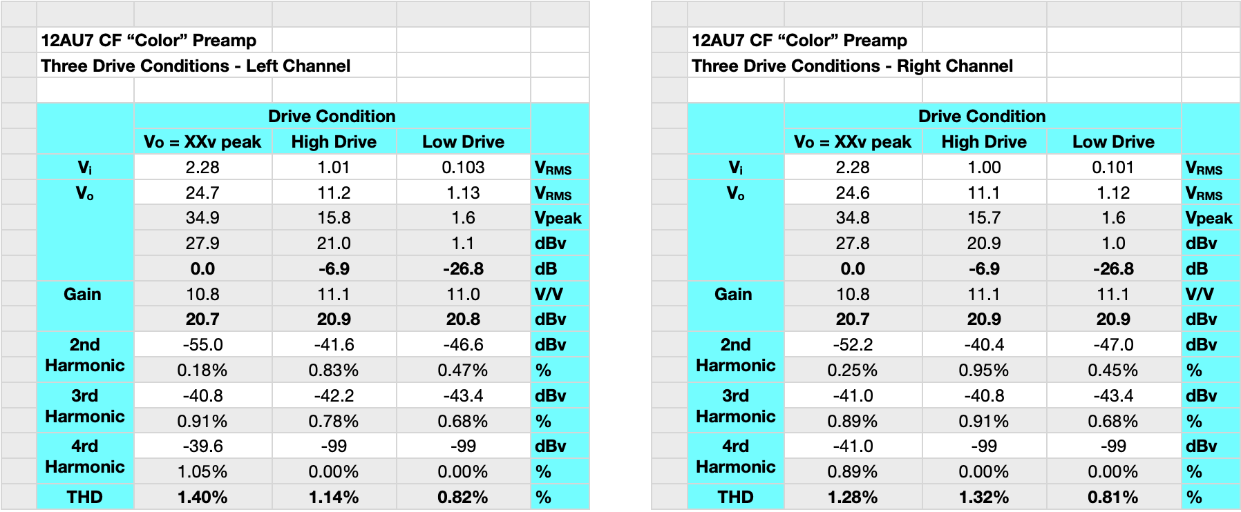
The high drive condition is 7.1dBv or about +9dBu. That’s a very stout signal. No line level source should ever go this high. And this was the point where the buffer just started to compress so I consider this a good representative maximum drive condition. The preamp can handle larger signals but the harmonic structure will begin to look more “transistor like”. You’ll also note that the stage gain is back at about 21dB. This means that the volume control at 50% is about 0dB and the total range of the volume control is a nice symmetric +/- 20dB. This feature alone makes this a very nice way to balance sources and amplifiers.
The bandpass of the preamp is about what one would expect. Here are the gain and phase plots.
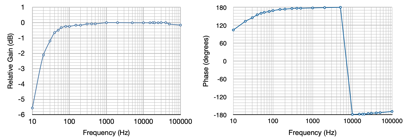
At the low frequency end, the amp rolls off gently starting about 50Hz. The gain is down ≈0.7dB at 40Hz, ≈1.2dB at 30Hz, and ≈2.1dB at 20Hz. At the high frequency end, the Miller capacitance doesn’t start kicking in until the frequency gets above 50kHz. The change of the coupling capacitors from 0.047µf to 0.10µf should help regain about a dB at 20Hz more or less. But frankly, this response is good enough as is that there really wasn’t any need for me to make the change in the prototype.
The last test was a listening test with the same class-d amplifier and speakers from before. The result was even better than last time. Frankly, I was shocked at the difference the improved buffer and the lack of pad made in how this little unit sounds. It takes a sterile sounding system and adds both warmth and depth. The preamp does exactly what I wanted. I very happy with the results.
This wraps up this little diversion project. This project effectively occupied the entire month of February. And even though the snow has returned this morning with 28°F (-2°C) temperatures, I feel like I really need to get back to the 6AS7 SET project. I’m not quite sure how I’m going to do that yet, but I’ll figure something out.
As always, question and comments are welcome.
Hi Matt,
With the input not connected to anything ( floating) When the Volume pot is rotated to maximum position, There is a noise above 2 o clock position…. Until 12 o clock position,there is no noise….Is this normal or it should be completely silent?
Vp
Normally the position of the volume control should have no impact on the noise level of the preamp. Depending on what is connected to the output, it is possible that there is a loading issue. This could occur if the downstream amplifier has a grounding problem on the input. Or there is an issue with the interconnect cables. Also be aware that it is possible to have ground loop is you are not lifting the signal ground reference of the preamp properly.
This post “Grounding Philosophy” covers the subject of ground lift and signal reference with multiple pieces of equipment fairly well.
Matt, can you be more specific about what parts were changed on this final version of the color preamp? Pot value, resistor values. Thanks.
The changes were exactly what I describe in the post. I changed the buffer bias point by changing the load resistor from 50kΩ to 10kΩ. This change restored the maximum allowable voltage swing into the buffer from the gain stage. I also removed the make shift 6dB pad from the input. Also, because the total range of gain variation had shifted with the pad insertion, I had altered the shaft position of the volume control so it would still be at 12 o’clock an the neutral gain position. With the pad removed I could again set the volume control knob in line with the true volume control shaft position. It is the same 10kΩ volume potentiometer.
All the correct circuit values are contained in the schematic posted on the 12AU7 “Color” Preamp project page. Also note that the 10kΩ buffer load resistors should be rated at 1W dissipation.
When reading these posts be keep in mind that when I discuss projects in the blog they are generally “in progress” when the posts are written. The color preamp started out as a simple time filler but evolved over about a month as I tested, discovered and correct design issues, and tuned performance. The final project page accurately reflects the final design and build.
Yes. I was talking about the Universal. Thank you for the very clear explanation.
Your adventure with this revised preamp prompts a question in my mind:
How did you settle on 250K for volume pot? I put a 100K in my current build (without cath follower), mostly because I have a plethora of those (dual ganged) in my parts box and it’s my default value. I checked cutoff frequency with either 100 or 250k and the 0.1 coupler and no prob with either, so you’re maybe thinking about loading……
Maybe this is a silly question, but one I’ve not pondered before myself. I always just stick 100K at input and move along…habits become reflex and so on.
I’m assuming that you are talking about the Universal Preamp and not the “Color” preamp. The volume pot in the Color preamp is 10kΩ.
For the Universal Preamp it comes largely back to AC plate loading with the control on the output. In the Universal Preamp at DC, the tube sees a simple 100kΩ load. However, at AC the plate load is a parallel combination of the 100kΩ plate load resistor and the 250kΩ volume potentiometer. This means that the AC load-line is rotated counterclockwise about the operating point. In this case the load line is ≈71.4kΩ. For the universal I was not comfortable going to a 100kΩ output potentiometer as this would reduce the plate load to 50kΩ which I felt was too low, especially for the higher gain triodes.
I could have gone higher to reduce the variation in plate load, but this would have driven up the output impedance to a point where it would have adverse effects driving a 100kΩ input impedance amplifier. So when all is said and done, it was a balanced design decision.