
An Outgrowth of Optimization
This amplifier was a direct outgrowth of the 6L6 Optimization Study. Having performed the study of the 6L6 tubes in an SE-UL configuration, and seeing the excellent performance which could be achieved, I decided to put the data into a practical application. This amplifier is the result.
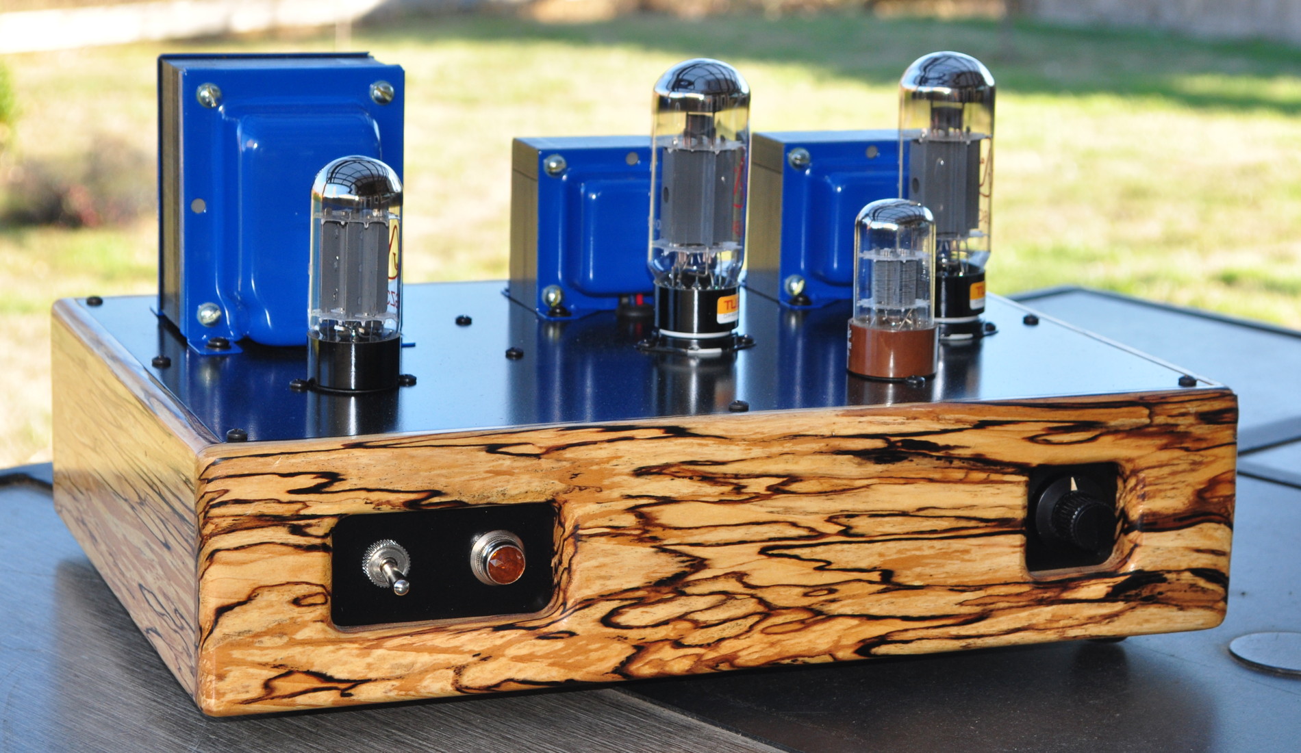
Those with sharp eyes may notice that this amplifier shares a marked external similarity with 6V6 Marblewood Amplifier. This similarity flows mostly from the layout of the top plate and the similarities in the tone and pattern of the two wooden chassis. However there are some major differences which make this a far different design overall. Also, whereas I tend to prefer to run 6L6 tubes in the Marblewood amp these days, this amplifier makes much better use of the bigger 6L6GC tubes.
The Electrical Design
The first step in putting the 6L6 optimization data to use was to pick an operating point for the power stages. One surprise from the 6L6 study was the discovery that the overall distortion was very low regardless of the operating point chosen. This allowed the operating point to be chosen based on other criteria. Here is the set of optimized operating point data from that study.
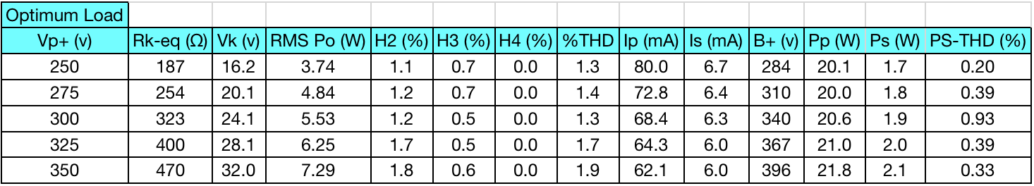
At this point I had a thought. Since I had already produced a number of lower power amplifiers I decided to maximize the power output from the 6L6s. Not only this, I wanted to be able to swap in KT88/6550 power tubes with no other modifications. So I chose the bottommost line from this table with a B+ of 400Vdc, a plate voltage of ≈350v, a bias voltage of ≈32vdc, and a total cathode current of ≈68mA.
This design point would yield in the neighborhood of 7W per channel of nice clean sound out of the 6L6s. It also turns out to be a reasonable point to operate the KT88 tubes. My test data from a KT88 with a B+ of 400v and a 470Ω cathode bias resistor showed a plate voltage of ≈350v, a cathode bias voltage of ≈36v, and a total cathode current of ≈76mA. This is near the middle of the KT88 UL plate characteristics curves at this plate voltage.
In order to achieve a reasonable end to end power sensitivity for the amplifier, I chose to design using the higher gain (µ≈70) 6SL7 as a driver in a single ended common cathode topology. I also chose an operating point which would allow the insertion of a 6SN7 with no modifications. This option would be advantageous for those using a higher drive level or those wishing to use a preamp with the amplifier. Here is the 6SL7 load line design.
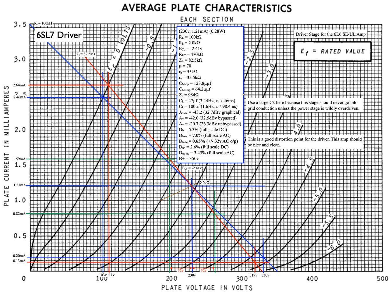
This 6SL7 operating point provides ample amplification and very good distortion characteristics for the driver stage. It also provides enough drive voltage to fully drive the big KT88s with a reasonable line level input.
After calculating the appropriate coupling characteristics, here is the final schematic (signal channel) I recorded for the amplifier.
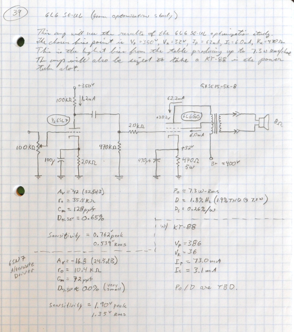
This is just a snapshot of a page out of my design notebook. The calculated design power sensitivities for both drivers are recorded in my notebook. The drive with the 6SN7 is a full 8dB lower allowing more voltage drive to reach full power. The calculated coupling capacitor (value not shown above) is 0.1µf.
In this schematic I also specified an Edcor GXSE15-5K output transformer. From the current levels involved I could have used the GXSE10 series but I wanted something else. One problem with UL amplifiers is the rather large effective plate resistance of the power tubes in this topology, which can limit low end performance. I chose the larger primary inductance of the 15W output transformers to help compensate for this. I also wanted the additional magnetic flux margin in the core of the GXSE15 to handle the higher flux from the KT88 bias point.
The power supply design for this amplifier was supposed to use a transformer I had on the shelf with an 800VAC secondary. I figured I could just use an appropriately large dropping resistor and all would be well. However, there was a hitch. The resultant no load DC voltage using this transformer was over 550VDC. This meant that I needed power supply capacitors rated at at least 600VDC for safety margin. These proved to be prohibitively expensive. So I decided to order a new XPWR178 transformer from Edcor with a high voltage secondary of 660VAC.
The no load secondary voltage of the new transformer was ≈700VAC. The Edcor power transformers are rated for specified voltage at full load. I knew this and had assumed it when ordering. This means that the no load dc voltage is in the neighborhood of 495VDC. As such, even though I have no intention of operating the amp without power tubes installed, I wanted capacitors (both filter and coupling) that could handle the voltage. For the filter capacitors I went with JJ ANH series electrolytic capacitors. For the coupling capacitors I went with Vishay 716 series capacitors with a 630VDC rating. Here is the resultant power supply schematic.

Note: I have added fixed 75Ω/5W resistors in series with the rectifier plate leads. This change is required to prevent the arc over of some GZ34/5AR4 rectifiers. This change is recommended for all builds of this amplifier design.
This design uses separate chokes on the power stages to provide excellent channel separation. The natural PSRR ratio of the driver stage in combination with a 30µf filter capacitor (the schematic above shows 100µf but I used a 30µf in the build) provides the channel separation in the driver. This amplifier also incorporates my now standard dimmable power indicator.
The Build
With the electrical design of the amplifier complete, it was time to think about the chassis. The wood I finally decided to use for this chassis was spalted alder. Here are the slabs as they came into my workshop.
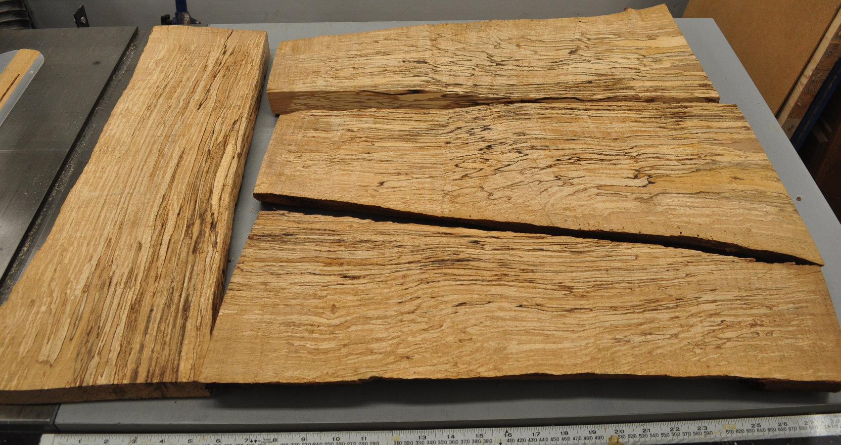
This particular wood has an interesting history.
This wood comes from a log cutoff that served as an anvil stand in my workshop for about 20 years. In 2015, when I was moving my shop across country, I removed the anvil and gave the wood log to a friend for his wood pile. I figured I could get a new log to use as an anvil stand anywhere I went.
He took the log and placed the cutoff next to his wood pile butt end down on the bare earth. And there it sat, in the rain and weather, for several years. Then a couple of years ago while cutting wood, he decided to cut the round. When he sliced the log lengthwise with his chainsaw he saw the spalting. So he slabbed the log and set the pieces inside his wood shed to dry. I was unaware of any of this.
Now, I had moved back to the same small town I left only a couple years later in 2017. So about a year ago, my friend came to visit and showed me the wood he’d brought. I decided that this was the ideal wood to use for this project.
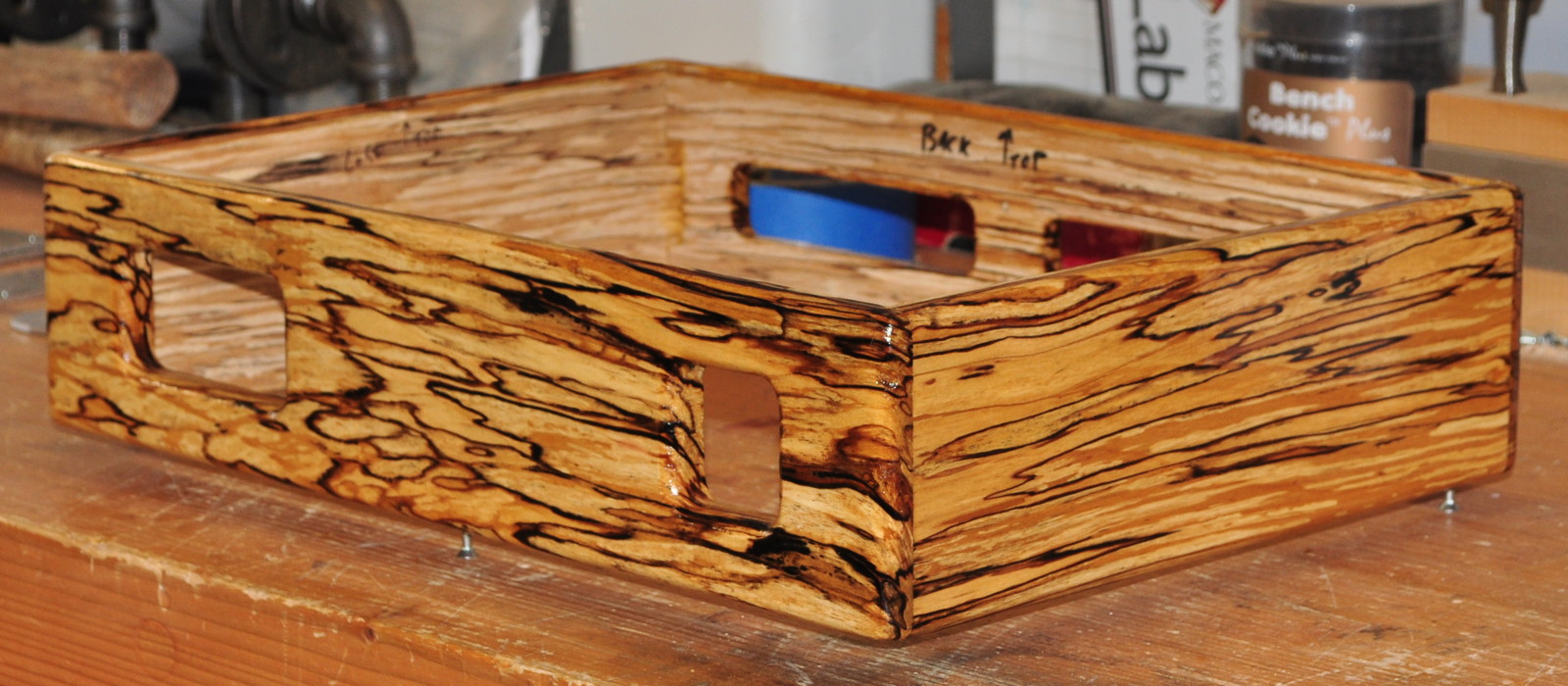
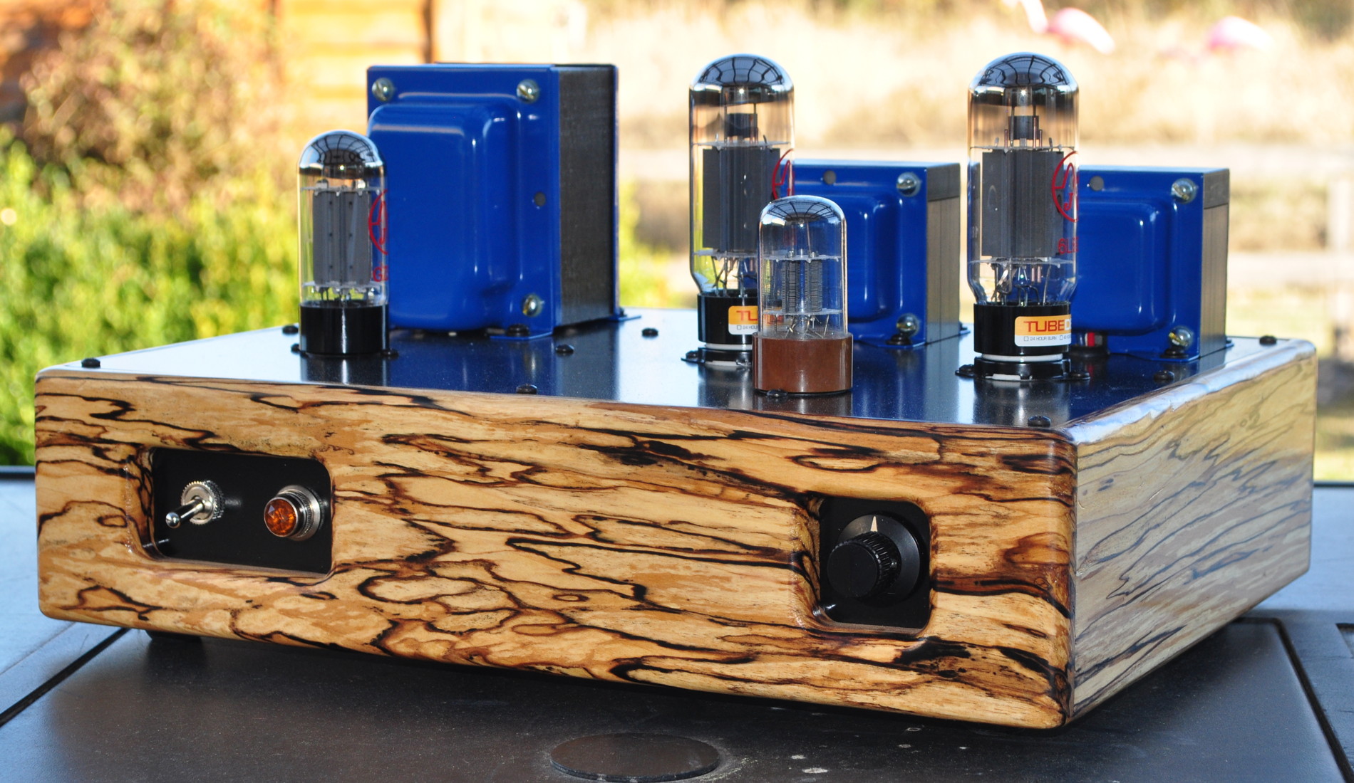
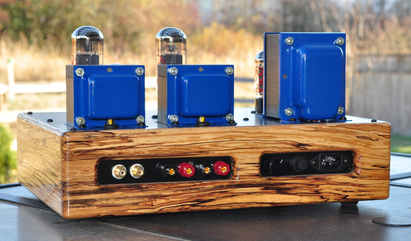
Here’s how those slabs of rough wood above look as a finished chassis with five coats of oil finish.
The layout for the internal of the amplifier was a little more complicated but I managed to fit everything in with a little room to spare. Here is the diagram of the internal layout.
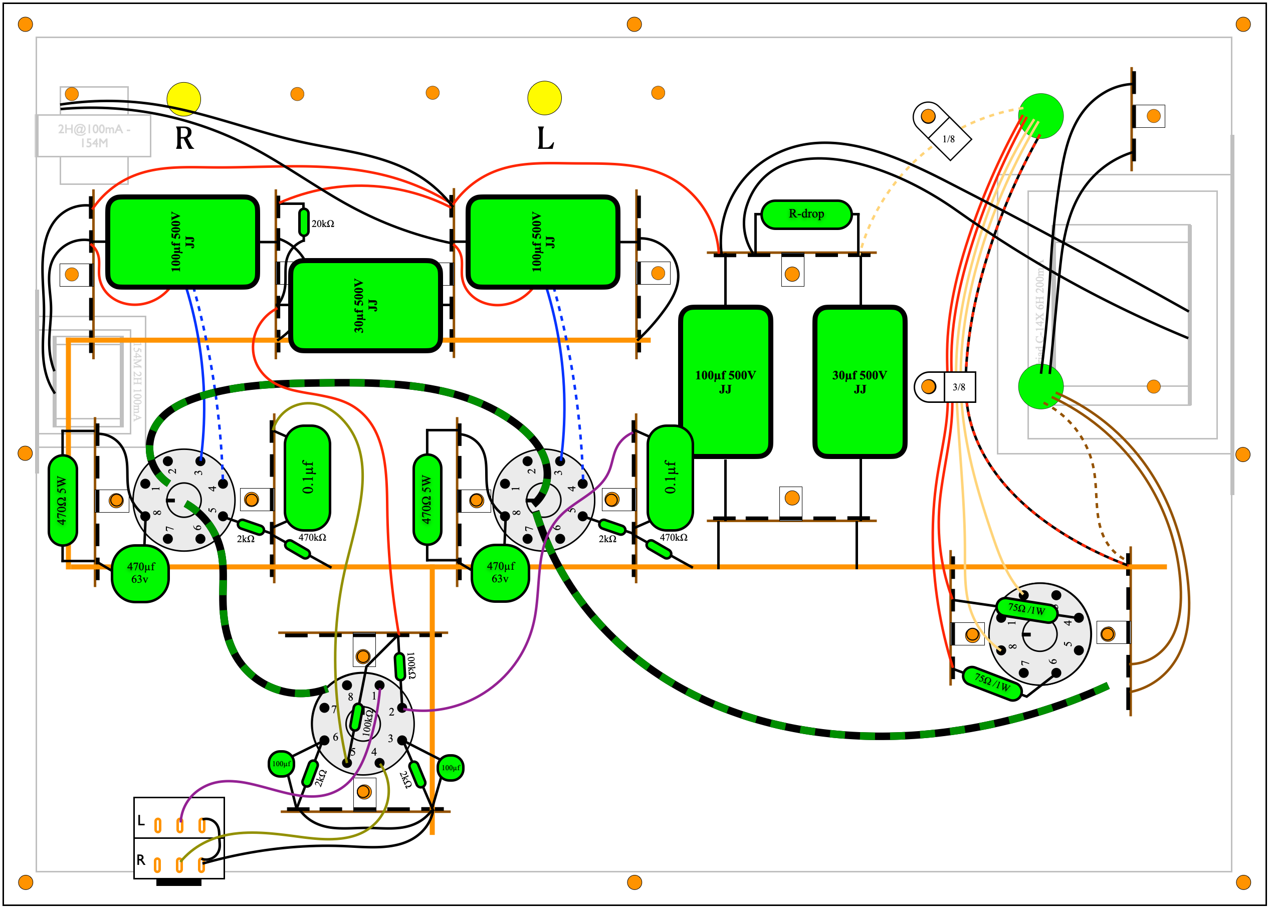
Note: Please note the addition of 75Ω/1W resistors in series with the rectifier plate leads.
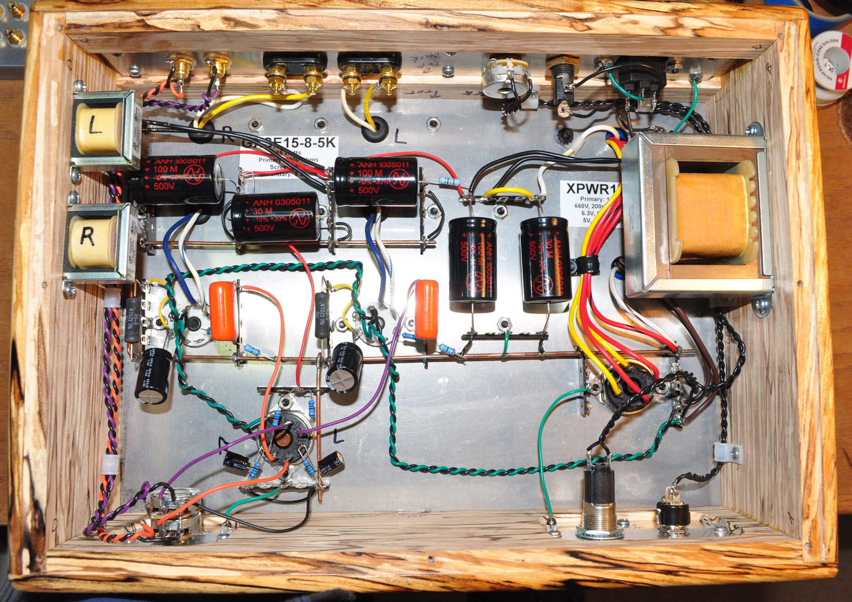
The main filter choke is on the right attached to the inside of the chassis. The two small 2H filter chokes for the power stages are on the left had side under the right channel output transformer, also attached to the chassis wall. Here’s what it looks like from the underside with all the wiring complete.
Testing
The first surprise of this build came when sizing the power supply dropping resistor. When I chose the XPWR178 power transformer, I had known that the B+ would be close to the target, but I had assumed it would be a little high. When I first applied power with no dropping resistor in place, the B+ at the power stage was ≈385VDC. This is about 3.8% below the 400v target voltage.
This lower B+ voltage doesn’t constitute a problem as it’s still very close to the target. However it does mean that no B+ dropping resistor is required. In the picture above, the bright yellow wire between the positive terminals of the two vertically oriented filter capacitors is where the dropping resistor would have been placed. Here are the resultant critical voltages at the the signal and power stages.
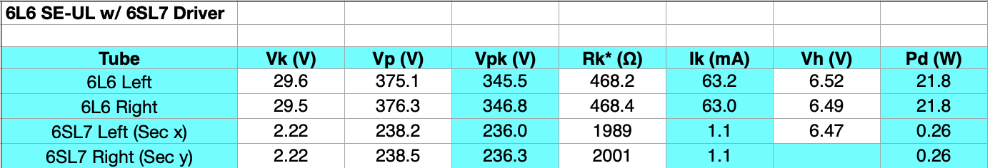
The drop in B+ only resulted in a less than 5v falloff in plate voltage on the power stages. The cathode voltage is slightly lower than target (≈2.5v or ≈8%) but not enough about which to worry.
The basic performance of the amplifier is very good and very close to the target. Here is the summary performance data for both channels.
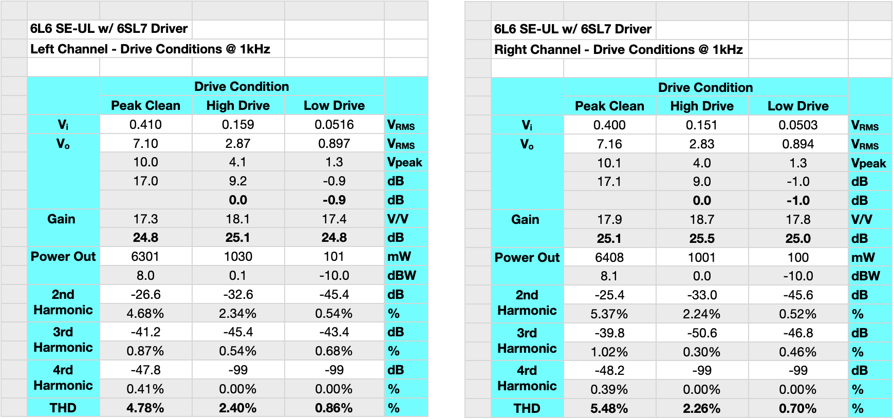
This data shows the performance for both channels at three different drive conditions. The first of these I call “Peak Clean”. This is determined from simply watching the output waveform on the oscilloscope and increasing the drive until I can just see some flattening of the output sine wave peaks. The other two drive conditions are the required drive for output powers of 1W and 100mW. This summary data is mid-band data taken at a frequency of ≈1kHz.
As can be seen from the data, the amp peaks out at around 8dBw or 6.3 watts per channel. It can obviously go higher than this, but this is where the harmonics really start to grow. Beyond this drive point the full set of harmonics (even and odd) start to grow and the sound of the amplifier begins to approximate that of a transistor amplifier. My target power was the 7.3W per channel of the optimization study. But with the falloff in B+ this is a reasonable result. The difference between 7.3W and 6.3W is only about 6/10th of a dB. Not enough about which to worry.
At 1 watt the amp is nice and clean with around 2.4% THD which is virtually all second harmonic. This gives the amp a nice full sound at moderate volumes. At 100mW the THD is well below 1% which is imperceptible under real world listening conditions. This makes the sound very clean and true at low volumes. These are excellent results and about what was expected in a full amplifier.
With the 6SL7 in place the amp is relatively sensitive requiring only about 400mv rms to achieve full power. This makes this amplifier easy to drive regardless of the source being used. The amplifier was tested for frequency response at about 1/2 a dB below the “Peak Clean” drive conditions listed above. Here are the full bandwidth relative gain and phase plots.
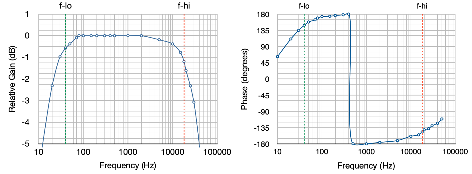
The 3dB bandwidth goes from ≈18Hz to ≈30kHz and the 1dB bandwidth goes from ≈30Hz to ≈17kHz. The low end rolloff at 20Hz is -2.3dB and the high end rolloff at 20kHz is -1.6dB. This is excellent performance for a SE-UL amplifier. Both the low frequency and high frequency roll offs are mild and well controlled.
The low end frequency performance shows the benefits of the larger 15W Edcor output transformers. This is due to the larger primary inductance of the 15W output transformers mentioned above. The other nice thing about these transformers is their low end distortion characteristics. These amplifiers are specified for a bandwidth of 40Hz to 18kHz. Below 40Hz there may not be enough cross sectional flux area in the core to support the waveform. This leads to low frequency distortion. But these transformers actually control this low frequency distortion rather well. Here is the distortions below 1kHz down to 20Hz.
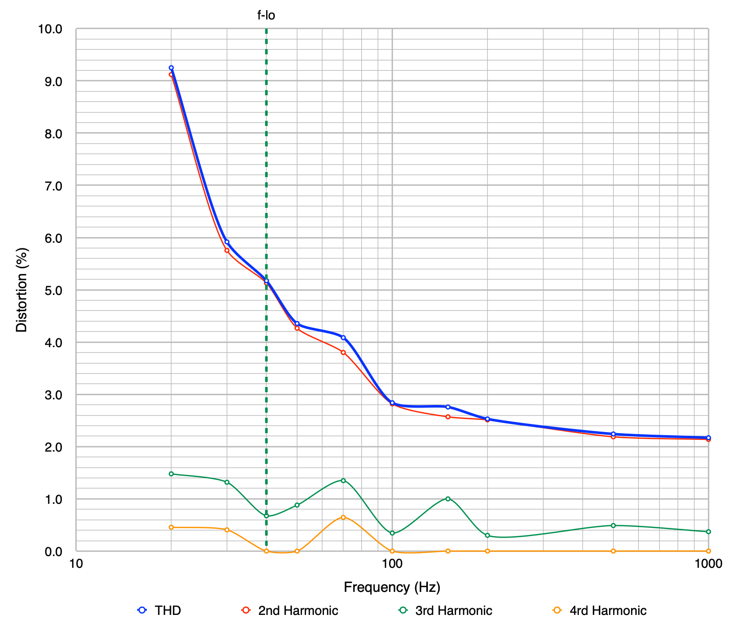
This is actually excellent performance for an amplifier of this type. There are two things of note in this instance. First is that the distortion is virtually all second harmonic. As such it is not discordant and is pleasant to the ear. The second is that it is virtually impossible for the human ear to hear this level of distortion below 100Hz. The result is an amplifier that has a clean and powerful low frequency performance.
Impressions
The most succinct description I can give is that the amplifier is clean, very fast, neutral in color, and musically powerful. It is an excellent example of the single ended UL topology. It is a solid performer with virtually any type of music but it really excels in the Classical and Vocal arenas. When listening to good classical scores I could easily pick out individual instruments and their details. When listening to vocals (even some Gregorian chant) the sound comes through crisp and true with no sign of blurring or excessive sibilance. Even the difficult overtones of choral voices came through clear and true.
The increased inductance of the output transformers did not have any noticeable effect on the speed and dexterity of the amplifier. The amp handled my test track for speed, Frederick The Great : Sonata in B-Flat – Allegro for recorder played by Michala Petri, without missing a single beat in the very fast, and very crisply played, score.
The amplifier reproduced bass heavy tracks with power and control and without any hint of booming or muddiness. Some sample tracks I used to test this included Not Fragile (quad mix) off the Bachman-Turner Overdrive “The Anthology” album and Cold Cold Heart off the Norah Jones “Come Away with Me” album. Both tracks have solid crisp bass lines intermixed with other instruments that really test an amplifier’s limits.
This design and build is an unqualified success. The amplifier sounds fabulous with crispness, precision, and power and without ever being fatiguing or straining on the ears. It is a pleasure to which to listen.
I would recommend this as a great “second amp” for anyone wishing to expand their skill and experience a bit. It also has enough power and precision to serve as a good main power amp in most systems in small to moderately sized rooms.
Configuration Options
There are two configuration modifications that can be made when using this amplifier. The first is that the driver may be substituted with a 6SN7 tube. This reduces the sensitivity of the amplifier by about 8dB allowing higher driving voltages or the use of a small preamplifier for tonal shaping.
The second modification is the substitution of power tubes. This amp will handle all the higher dissipation members of the 6L6 family including the 6L6GC and the 5881. It will also handle the KT88 and 6550 tubes without modification. These power tubes will be operated far below their limits but will provide good performance and long life.
So let me know what you think of the 6L6 “Spalted Alder” amplifier.
Hi Matt,
Your pages are an inspiration. Wondering about a couple little things:
You mention trusting the volume pots not to open circuit, but what is the down side of adding a 1M grid resistor to ground on the input of the voltage stage as a protection against this (besides extra cost + 1 component)? Secondly, have you tried the famous “red LED” to replace the cathode resistor – or do you have any opinions on it?
There is nothing wrong with bridging the grid to ground with a 1MΩ resistor. If you don’t trust your potentiometer, go right ahead. There really is no downside to doing this except the slight additional complexity.
As for the LED biasing, I’m just not a fan of this. I don’t like adding silicon to my tube amps unless absolutely necessary. And personally, my opinion is that cathode biasing produces a superior sounding amplifier with respect to diode/LED biasing or battery biasing. It’s so simple to calculate the appropriate resistor value I see no reason to add forced biasing for an inferior solution. I’ll get off my soapbox now. 🙂
My own copy of your Spalted Alder has been performing incredibly. Matt, I can’t thank you enough for all the work you put in to your blog. I finally updated with the 75ohm resistors. I noticed inconsistencies on the resistor rating mentioned; 1 watt, 5 watt and a picture of 1/2 watt resistors (probably used for testing). I had 1 watt on hand, but they quickly reached 300°F+. I think I see why you landed on a 5w rating. Thanks again!
Glad the project has worked out. Yeah, the dropping resistors were a story all in themselves. The story is in the blog post “That Didn’t Go Well!” from December 2024.
I forgot about that post!
Hi Matt-
Great Build- Fantastic result! Quite the looker! A most excellent detailed analysis and instructional writeup. Thank you for that. I just had a couple of questions, and sorry if these have already addressed-
I certainly like the use of the GZ34/5AR4 tube- the delayed filament warm-up sure makes life easier on your bypass caps, by limiting the over-voltage surge before the outputs warm up. Have you had any issues with the JJ GZ34 above and beyond what you might have with a NOS tube? I have heard mixed reviews of the JJ tube.
Putting the 100uF cap across the 6SL7 2K cathode resistor will maximize gain, but at the expense of better linearity afforded by cathode degeneration. The final result shows a ~24dB overall gain with a 400mVrms input signal to drive to “Peak Clean”- A very sensitive amp, but still reasonable- as you say, “easy to drive” for sure. I was just curious if you experimented with removing this 100uF cap, and I’m curious how the overall THD figure might change without it.
Have you been happy with the orange drop style coupling capacitors? With my practical background and my ears, I’m not so choosy when it comes to capacitor types, any poly pretty much sounds the same to me, (I probably could not even hear ceramics in a blind test), but when I build amps for sale or showcase, I feel pressure to upscale the caps to a Mundorf, etc. What is your opinion on this?
Thank you for your time, and again great build! -Warren (wparks on Audiokarma)
The GZ34 is a sensitive tube. But with the 75Ω resistors in place I have not had any issues with the amp. You can also just plug in a 5U4GB without any issues. Peak power will drop a little but under most circumstances, you’ll never notice.
The driver gain is not really an issue with this design. I was shooting for a more sensitive amp when I did the original design. But if you want less sensitivity, you can just plug in a 6SN7 driver without any changes. This lowers the sensitivity by ≈8dB. You are correct that removing the cathode bypass will marginally reduce distortion, but it will also change the harmonic structure. I’m not a fan of the trade off.
Capacitors is a topic which generally blows up fast. As such I usually avoid have such discussion in a public space. I’ll send you a private email on the topic.
Hi Matt,
First off thanks for all the work, this site is great and a huge wealth of information for a semi novice builder. I have some NOS 6550’s I was gifted and would will most likely be tackling this build in the new year. I’m currently running two mono Heathkit WAP2 as preamps. My question is this, I’d love to power them off this amp with octals, akin to the Heathkit and Dynaco setups. Each preamp uses 300v DC @10ma and 6.3V @ 1A. It seems there is “space” for the extra 20ma @ 300V but the heaters would definitely overload the transformer. Would you suggest bumping up the PT to a larger one or simply add a small 6.3v transformer inside the chassis?
Again, thank you for this site.
Best,
Helge
Either option is on the table. If you choose a different power transformer be sure you have the skills to tinker with the power supply design to get the B+ right. Personally, I’d likely just add a second filament transformer for the new tubes.
Don’t forget that the additional draw will affect the B+ voltage. With the XPWR178 transformer I chose, Rd was just a jumper. Another 30mA of draw will lower the B+ somewhat. But going to a transformer with a higher secondary voltage (i.e. >660VCT) will require higher voltage ratings on the power supply capacitors. Everything is connected.
Hi Matt,
Greetings from the UK. Thanks for your wonderful website. I built the Spalted Alder amp and its been performing wonderful, recently I ran into the blown rectifier plate resistors issue. I’ve replaced them with the beefed up 75ohm, 5w but now I am getting a popping and interference sound from one channel. On inspection everything appears as should be, so I am wondering if you may have ran into this issue and are there any pointers you could give me on what may be the culprit? Sorry to ask; I managed to build the amp using the schematic and photos but not clued up enough to fault find with much competence.
Thanks Malcolm
In all likelihood the blown rectifier plate resistors and the “popping and interference” sound are unrelated. The first thing I’d recommend is to swap the to 6L6s and see if the problem changes channels. If it does, a bad 6L6 is the issue. IF it doesn’t change, I would then replace the 6SL7 and see if the problem goes away. If neither of these two things change the behavior, send me an email and we’ll discuss further.
I hope this helps.
Hi Matt,
Thanks for the swift reply. I’m actually using a pair of KT88 which I have swapped and the issue remains in the same channel. I’ll get hold of a new 6SL7 and see if that fixes it. I’ll let you know how that goes.
Thanks again
Malcolm
BTW, your Spalted Alder amp is very beautiful!
Hey Matt,
This is almost exactly the type of amp I’d like to build for listening to all my old vinyl. I have been thinking of a way to incorporate wood surrounding metal base plates, and you have proved it can be done. Just so you know, I was introduced to you by King Fan at the TDPRI forum.
I have a lot of really beautiful guitar wood. My thought was to take this 1/4″ wood and laminate it to 1/2″ quarter sawn white oak, for just one example. I’d like to use either brass or stainless steel, or perhaps a combo of both, for attaching components.
Sound doable?
Thanks in advance!
Robert
This all sounds very reasonable.
Thank you Matt!
I have a tubelab sse sitting on the shelf because I was never very impressed with any variation of it. It’s time to repourpose the nice Edcor iron and this build looks perfect. I have a pair of EL37’s I would like to use here. Are there any considerations for this tube?
The EL37 is kind of an esoteric tube and far different than the 6L6 and KT88 for which this amplifier was designed.
For starters, the EL37 is a true pentode not a beam power tube. This gives the UL response a significantly different character. It also requires a far lower plate load (like its smaller cousin the EL34/6CA7). I would recommend an output transformer in the 2kΩ to 2.5kΩ range. I have no idea about appropriate bias levels for this tube as I’ve never worked with one. I wouldn’t worry about the power supply dropping resistor. With the specifications of the EL37 you can let the B+ run hot. Make sure that your filter capacitors are appropriately rated.
The best way to deal with a major substitution like this is to do some measurements on the tube to determine the best operating point. If you read up on my optimization work for both the 6V6 and the 6L6 this should give you some ideas.
Hi, is it possible to use 6P3S instead of 6L6GCs given that the supply voltage is 400V? For the 6P3S, it seems the max VA is 350V.
Thanks
Yes. Plate voltage in this amp is well below the 400V level. Usually running between 325v and 350v.
off the top of your head,. what sort of changes would this design require to use 807 in stead of 6L6GC?
thats a beautiful amp
Short answer: a lot!
There is a persistent myth that the 807 is similar to the 6L6. This is not true. The tubes have very different characteristics.
When I experimented with 807s in UL mode I found that they did much better at a plate load of ≈2.5kΩ and a much hotter bias point. I think I settled at about a 300v plate voltage and about 80mA of quiescent current. This is about 24.5W of plate dissipation. This represents a cathode voltage of ≈25v using a cathode bias resistor of ≈300Ω. At this point the power into the output transformer was about 8W (maybe 6.5W to 7W at the speaker).
Therefore changes to this design would mean an entirely different output stage and a power supply with significantly higher current capability and slightly higher voltage (B+ ≈325vdc). This is really an entirely different amplifier.
My experiments drove me to the conclusion that the 807 in audio usage is better run in triode mode. The power is a little bit lower but the tonal characteristics are far better. I talked about this in the post “A Lesson in Power Stage Distortion” back in January of 2017. (Wow, that was a while ago!)
I hope this answers your questions.
Matt, Thanks for all the work you do to show the layout as well as the final product. In the layout it looks like the power coming into the rectifier tube hits a terminal strip and then to the tube base through resistors. In the picture, it looks like the power goes straight to the tube base. Was this difference because the B+ voltage was lower than your 400v desire?
You are correct. The picture of the internals on the main page is older. There were some problems with the GZ34 rectifier and I realized that the original design did not have sufficient rectifier plate load for reliable operation. I talked about this back in October of 2024 in the post “A Slight Revision to the 6L6 “Spalted Alder” Amp”. The wiring of the rectifier tube now looks like this:
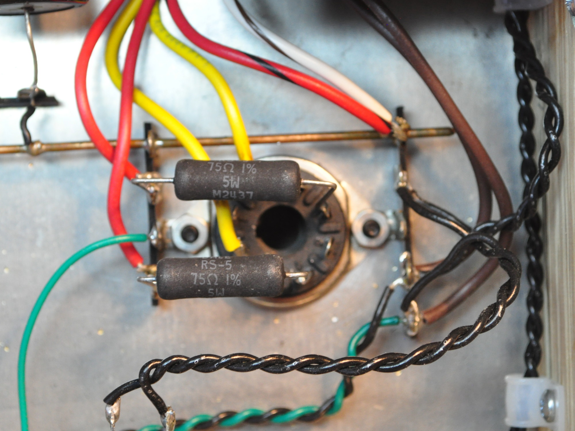
That plus the two linked blog posts should clear things up.
Unfortunately I don’t have a shot of the entire internals with the 75Ω/5W resistors in place. I’ll add this to my list of things to update when I get the chance.
Thanks for the photo and the link to the blog post. I actually replied to that post; so, I should have remembered.
I have seen guitar amps with rectifier diodes mounted the same way. Are they there to stabilize the tube the way the plate resistors do?
The primary function of the resistors is to dampen ringing in the current waveform when conduction cuts off. There is actually a significant capacitance between the plate and cathodes in these big rectifier tubes. There is also an inductance in the power transformer secondary. Without a minimum resistance to damp resonances, the tubes can arc when the current cuts off. The data sheets generally give an indication of the minimum value required. In my case the transformer secondary resistance was insufficient for the GZ34 so it needed to be increased.
The addition of solid state rectifier diodes in series with the rectifier plate leads is just bad practice. They don’t do anything positive for the operation of the supply and they do not provide any type of protection. There’s lots of internet bloviating about such diodes; virtually all of it completely vacuous. If I find such a thing in a pice of equipment I’m working on, I remove the diodes and redesign the power supply to fix any design issues it might have had.
Thanks for the info. It is good to know!
Hello, Matt! I thoroughly enjoy your website.
I’m planning to build this amp, but I am not good at computation and design. I have on hand a 700V CT power transformer and a 10H choke. You recommend using a 5U4G, which I will do. I just want to be sure that the 10H choke is good to use. If it is, should I use 2H or 1H for the smaller chokes? Otherwise, I will get a 6H choke and follow your design as is past the rectifier. And might I need a dropping resistor after the 1st filter capacitor?
Thank you very much for your work and for sharing the fruit to us.
Cheers,
Perry
Go ahead and use the 10H choke for the primary filter. It will work fine and just give you a quieter power supply. I suggest you stick with the 2H chokes on the individual power stage filters. In addition to B+ filtering, these chokes provide isolation between the power channels. You could use 1H chokes but the channel separation will suffer by approximately 6dB.
If you are using the 5U4GB you will likely not need a dropping resistor after the first capacitor. However, with the 700VCT transformer you will need some additional resistance in the rectifier plate leads. The specification for the 5U4GB requires at least 36Ω per plate at this voltage level. I don’t know what your transformer provides. You can either measure the transformer secondary resistance and fine the minimum required resistance or just insert one. Personally, I would simply insert a 50Ω/1W resistor in each plate lead and that will take care of the steady state and power up transient conditions. Prototype your power supply under load and make sure that the startup transient voltage does not exceed 500V. If it does, the first capacitor should probably have a 600 VDC rating.
Hi again, may I ask you which software do you use to draw chassis and wiring layouts?
Thanks again
Sajad
I use the “Pages” application on a Mac. If using a PC then I typically just use “PowerPoint”. The best answer is to just choose something you have available and then practice with it until you’re very familiar with the layouts and tools. In my experience, the dedicated CAD type software packages are not worth the cost or effort unless you use then very regularly (like many time a week).
Thank you so much, yesterday I found a free software called “Diy layout creator” which have a lot of component models for P2P wiring.
Thanks again
Love the alder frame, very nice! Has anyone voiced concerns about operating the 6L6GB at these elevated voltages? RCA states maximum screen voltage as +270V, and in triode mode, maximum voltage on the anode/screen is +275V. I have a good number of NOS 6L6GB, but it’s difficult to find a home for them in most 6L6-type amplifiers.
The power tube plate dissipation in this design runs between 21 and 22 watts. That is too hot for a 6L6G or 6L6GB. This amplifier was really designed for the more modern 6L6GC and 5881 type tubes.
If you really want an amp that makes good use of the 6L6G and 6L6GB tubes, I suggest the Marblewood design. That amplifier performs very well with the lower power 6L6 tubes and sounds really good using them. The performance using the 6L6 in the Marblewood is included on the project page.
Hi, awsome project as always, I had a question regarding this project; Is it possible to use 6L6 in this amp in triode configuration, i.e. can I simply put a tride/UL switch for the screen of 6L6, or should I change the load impedance or cathode resistor value to be able to do this?
First, I am going to state unequivocally that I actively discourage the building of “switch mode” amplifiers. These are amplifiers where switching is used to go from one power stage topology to another. In general, only one configuration will work well and the operation of the others will be compromised. This tends to lead to lots of false impressions and incorrect data about what topology/tube/load/configuration combinations work better under what conditions. In general, I encourage people to first investigate what characteristics they want an amplifier to have, then to chose a topology and design which best produces those characteristics.
All that being said, in this amplifier the 5kΩ load and 470kΩ cathode resistor will work with both triode mode and the UL mode topology. This amplifier design was a result of the 6L6 Optimization Study. As such that’s the desired design point. However, the amp will work with these same values with the 6L6 screen grid strapped to the plate. It won’t be as rich as most SET configurations as the cathode resistance is a little too low in my opinion. But it should still be capable of about 4W per channel with moderate tonal color.
So yes, you can do that and still get “acceptable” results. However, it is not something which I ever recommend.
Thank you so much for your great explanations, Actually I was thinking about a DPDT switch which switches screen from UL tap to the plate, and at the same time switches between cathode resistor for UL and triode mode.
So what values of cathode resistor and cap do you suggest for SET 6L6 with 5K load and B+ of 400V?
Thanks again
Sajad
I would probably go with something a little higher to get a better compressive operation at higher drive. Something in the neighborhood of 560Ω. Although, to be honest you probably wouldn’t notice the difference between the current 470Ω resistor and the 560Ω. The differences would be subtle.
Thank you so much
Hi – I made myself a copy of this — I call it the “CONN job” as it was a salvage from an old CONN organ. The power transformer is hefty – I had 3 available 6.3V supplies (1-6.3 and 2-12.6 with a center tap) I chose to split the 12.6 between the power tubes and use the standalone one for the preamp.
A 470ohm 15W resistor plus the chokes got me to within 2V of 400 :). I did not use a choke on the main PS section (cost and space) just a 1H on each channel – so its sort of a C-R-C-L-C and is very quiet. I used the open frame Edcor 15W OPT’s (cheaper and smaller to mount than the pretty blue ones).
I’m using a 6SN7 preamp tube (had one as I bought two when I built a lacewood2.0 earlier) and the B- it gets is lower, about 325V vs target 350V. Could that be the difference in preamp tube? or should I tune that 20K resistor a bit to be closer to 350V?
Other than that this thing rocks. This one will be going to the music room soon to be hooked to a Mackie mixer driving –> DBX Driverack PA processor –> Electo-Voice SP15A speakers/horn mid+tweeters — can’t wait, but currently enjoying with my bookshelf sized speakers letting it burn in for awhile.
I’m glad that the design worked out so well for you. My “Spalted Alder” is in my living room and gets hours of usage every day.
The slightly lower B+ on the driver stage when using the 6SN7 is perfectly normal. The 6SL7 driver draws about 1.2mA and the 6SN7 in the same socket will draw about 2.3mA (per triode). The difference in total draw means the the B+ is a little lower with the 6SN7 installed. Even so, it still has lots of headroom.
Thanks for the feedback. One last topic that I’d like your thoughts on is startup voltage overshoot and the need for a ‘soft-start’ to let the other tubes warm up before the HV kicks in. I was thinking of adding a momentary open pushbutton switch on the center-tap I could hold down for 5-10 sec when amp is first turned on to let the filaments warm up. My 5U4GB is driving over 500V for few seconds on startup, the caps are rated 450V in this build. I’ve also heard of folks snubbing standby switches with a resistor to not arc the switch contacts on guitar amp forums.
I’d approach the problem a different way. I suggest you use a GZ34 rectifier which has a much slower warmup and then increase Rd to get the final B+ voltage you need. This should take care of most of the overshoot.
The problem with switches and the like is they don’t get used after a while. The design should be stable and safe without intervention. Was there a reason you did not use the 500V rated capacitors?
Cap choice was just what I already had on hand, Rectifier tube came from the organ amp as did the 6L6GC tubes. Salvage/re-purpose project.
Luckily I’ll pretty much be the only one using it so I think I’ll switch it for this build, but I’ll be using the slow warm up rectifier tubes for future builds to avoid this issue.
Also, thanks for all the great characterization work you’ve done. I’m retired semiconductor yield / NPI engineer, nicely done.
Hi, I I plan on building this amp after I finish a preamp build.
I have a.few 6L6’s some Tung-Sol 5881’s OS and new manufscture, and a few Russian 6P3S-E’s and a few KT-77’s
Is there any reason not to try the KT-77’s in this amp?
I have an amplifier that can use EL-34 types along with KT-88’s and 6550’s.
Thanks,
Paul
I have not performed any testing of the KT-66 or KT-77 in this design. Whereas I don’t have any reason to think that they wouldn’t work, I’m not sure. The voltages and currents should be all within range. The only unknown is how the tubes will bias with the 470Ω cathode bias resistor. If you want to try them I strongly suggest you try to power up the amp with one and monitor the cathode bias voltage as the amp comes up to make sure the voltage, current, and power parameters are all within an acceptable range.
Thanks. I’ll definitely do that.
One more question. What size is the chassis?
I like the layout drawing, only it does not have dimensions.
Thanks in advance,
Roger
Here is the dimensioned drawing to the top plate.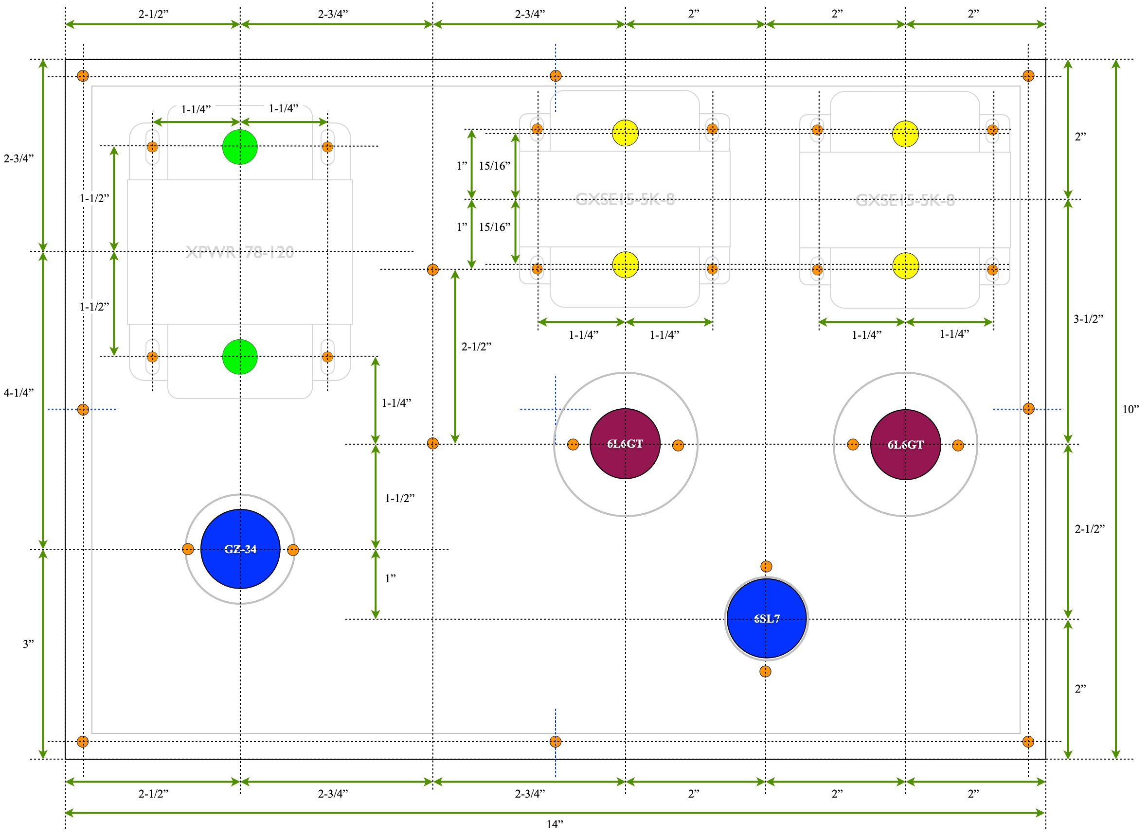 and here is a direct link.https://www.cascadetubes.com/wp/wp-content/uploads/2023/09/6L6-SEUL-Final-Layout.png
I just noticed that the hole separations for the sockets are not shown. For the sockets I used this dimension is 1-1/8″.
Hi.. I’m building a parallel SE 6L6 …so what would be the output transformers primary impedance…2k5??
The short answer is yes. If you are trying to use this data.
Vacuum tubes are basically voltage controlled current sources. Since paralleling two tubes doesn’t change the voltages it just doubles the current. If the load is shared then to retain the same voltage distributions, the load impedance needs to be cut in half.
Anyone put together a BOM for this?
Roger
Yes. Here is the link to a PDF file.
6L6 Spalted Alder Parts List
I believe that this is complete. Please note it does not include the chassis.
Thanks, that is a big help. If a solid state full wave rectifier was used, wouldn’t the B+ be a little higher, maybe even slightly over the target?
I am a fan of SS full wave, but am prepared to go with the tube.
Roger
I strenuously recommend against using solid state rectification in this design. The no load voltage of the transformer is around 700V giving almost 500v on the B+ line at no load. By using a GZ34 rectifier (technically a unipotential cathode design rectifier) the rectifier warms up at similar speeds to the power stages. This characteristic limits the power-on transients on the B+ and reduces stress on the filter capacitors.
I occasionally use solid state rectification on small projects but mostly avoid it these days. Even on small projects there are lots of options for small tube rectifiers. In addition to the 6CA4 (EZ81) I like to use the 6X4 (EZ90), the 6BW4, and the 6203. Sometimes, in very low draw circuits, I have even used a 6H6 for lower voltage and low current draw (<10mA) circuits.
First of all thanks for sharing your experiences online through this website and through the forums – it has been very helpful to show people like me how to design and build are own tube amps.
In many of your designs you have the driver tube running at quite a low current. Do you have any concerns about the driver tube not being able to drive the miller capacitance of the output tubes at high frequencies (slew rate limitations)? I have read that this can be a problem but I don’t know the math. I have read that with El34’s and Kt88’s 8-10 mA is recommended. What is your opinion?
Nope. I have no concerns whatsoever. And for good reason, it doesn’t matter. Not at all. Not even a little bit. The entire discussion of “slew rate” in audio amplifiers is a red herring. Please let me explain.
Driver stages in audio amplifiers are voltage amplifiers. And the first rule of voltage amplifiers is that they don’t supply power. So you should never worry about the power stage sinking current from the driver. What you have to do is deal with the input capacitance of the power stage. This is done by designing for the high frequency corner frequency based on the circuit impedances. It’s a simple single pole rolloff and quite easy to do. First you calculate the Miller Capacitance thus: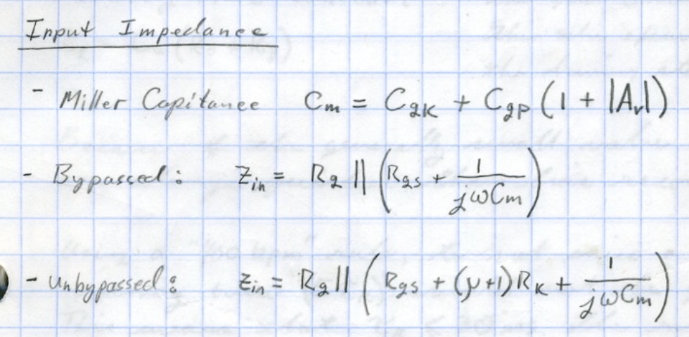
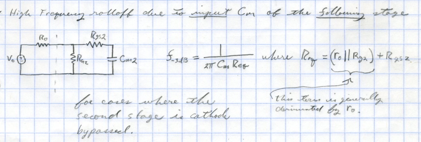
Once you have the input impedance of the power stage you simply set the high frequency rolloff frequency with the coupling resistances. Like this:
The whole discussion about driving audio amps with square waves and such is NEVER required. And “slew rate” is something only concerning the DC step response of instrumentation amplifiers. For audio amplifiers, simply set the high and low frequency rolloff points and those numbers completely describe the transfer functions for ALL waveforms. With those two numbers you can literally draw the square wave response without ever measuring it.
When somebody starts talking about slew rates and square waves with respect to audio amplifiers, it just means that they never learned Laplace transform analysis and Fourier analysis. Most of the discussions of “slew rate” I’ve seen on the internet are not only wrong, but usually miss the most fundamental points of circuit design and analysis.
My advice is from now on simply ignore any discussion of slew rates when talking about audio amplifiers. It’s just something that people discuss on forums because they don’t really understand how circuits work.
I am no expert, so please be patient.
I tried to use a couple of load line models to copy your 6SL7 operating point, and it comes in close enough for government work. However, when I try to use the voltages and resistances in that circuit with a 6SN7, the models do not look so good.
So, the reason I am curious is that I would like to build this as my third amp. But I want to acquire a turntable and a phono-preamp stage for this so I am thinking I want the 6SN7 version. Perhaps not.
Maybe the best way to look at it might be to use a higher R potentiometer, so the input volume control will represent a reasonable range of control over the volume with nominally higher input.
Thoughts?
Roger
I don’t know what you mean by “… do not look so good.” With no changes, the 6SN7 biases at 122v, 2.28mA with a grid bias of -4.6v. The distortion is well controlled and it can still drive the power stage to full output with an input voltage of 1.35v-rms. I have run this amp with a 6SN7 driver in the slot and it sounds great.
Your phono preamp should output a typical line level signal so I don’t understand your concern. Remember if you increase the size of the volume control, the high frequency response can suffer. See this post: Volume Controls and High Frequency Response.
My recommendation is to build the circuit as designed. It should work out fine.
Matt,
Thank you. My efforts to understand the simple replacement of the 6SL7 with the 6SN7 were to use the same voltages and resistances. I guess I do not understand how given the same cathode and anode resistors how the bias voltage could go from 230 to 122. I guess I have a lot more to learn. Thank you for your feedback. I will build this as designed with the 6SL7.
Ok, using another model, I was able to define both anode and cathode resistances. Substituting the 6SN7 got the values you quoted.
Thanks again,
Roger
This is one reason that I always draw my load lines by hand. I have never trusted either spice nor on-line models. Just too many unknowns.
Maybe I missed it, but which 6L6GC id you use on the 6L6 optimization, and which did you use on this build?
Just curious what you think of the different offerings of 6L6GC tubes available today, as new manufacture.
Roger
In the 6L6 Optimization Study I used a brand new JJ 6L6S tube. I started with a used 6L6 but didn’t like the way it was operating. IN this amp, I’ve used new JJ 6L6S tubes, some NOS GE branded 6L6GCs, and a pair of Russian 6P3S (6П3С) tubes. All have performed well in the amp.
Of the new manufacture 6L6 class tubes, for audio reproduction (i.e. not guitar amps), I hands down prefer the JJ 6L6S. To my ears they have the best sound, have reasonable lifetimes, and I’ve never had a problem with one. I am also warming up to the Tung-Sol new production 5881. I find these a little warmer than the JJs with a nice full sound. Now these new production Tung-Sol tubes are new Russian tubes very similar to the 6P3S (6П3С) tubes I referenced above. The Sovtek and TAD seem alright. Electro-harmonix can be good, but I have a history of getting bad, marginal, or noisy EH tubes so I generally only buy these from dealers with a good return policy. I generally stay away from the SINO tubes due to inconsistency problems. Although I’ve heard that the Genalex Gold Lion KT66 is an excellent tube but I haven’t verified that for myself.
I want to caveat that these are just my impressions. Your experience may be different. I hope this helps.
I just wanted to thank you for posting these projects. I’m scary new to tube amps but not to audio or basic electronics. I have wanted to build an amp of some sort from childhood so this is important to me at 49. I was recently hit with the Tube Bug and now I’m obsessed with the idea that people can build these at home. Not a corporation with machines and robots, but a dude with a soldering iron and the will to learn and need to build. That’s a huge realization for me and by studying your posts and reading books and soaking information, it seems less out of reach daily. I can do this. I will do this and taking the time to explain and show clear pictures and diagrams is huge for me. So thank you. Your work has not gone unnoticed or worse, unappreciated.
Thank you for your kind words and I’m glad you are enjoying the site.
If there is anything I can do to help please feel free to let me know.
Hi Matt
Been roaming about the site for a while. It is informative n nutritional engineering.
So happens I have a 6L6 SET amp years ago outputing 4watt only.
The circuit is similar with yours. Now I would like to upgrade it to the one as yours.
My plan is as following,
The primary will be 600v CT to replace the 560v.
Add two chokes to the channels B+ in addition to the main one of 5H/200ma.
Other parts values are more the same except:
The signal input cathole R is 1.2k yours is 2k.
The power tube cathole R is 270 ohm.
The 1k R is connected to the grid of power tube from the input plate.
At present I’m using 12ax7 in parallel but would like to change to 6sl7 as yours.
I’m planning to use Hammond 372 FX 600v 173ma as start primary.
Q 1, do I have to follow your values in those cathole n the grid?
Q 2, I just need to have around 6watt from it.
Any suggestions or comments.
Thanks for your time.
Robert ip
The most important thing to realize is that if you want this performance then you need to follow the schematic as much as possible. I’m assuming that your output transformers have UL taps for the screen grid connections. Without seeing the schematic of your current amp, I am assuming from what you’ve said that this is a major upgrade.
Changing from parallel 12AX7 to 6SL7 for the input sections will require increasing the cathode bias resistors to 2kΩ. Otherwise your bias will be too low and the amp will overload easily. The power tube cathode resistance is also critical. This needs to be 470Ω and needs to be at least 5W.
Also, the Hammond transformers are rated differently than the Edcor. I would suggest that you use the Hammond 376X instead of the 372FX. The extra 40V of secondary voltage will allow you to get to a B+ voltage of 400V more easily. Without a B+ very close to 400V you will not get to 6W output power. Remember that you will have to calculate the value of Rd in the power supply based on your resultant voltage and current draws.
I hope this helps.
Thanks, will follow suit.
BTW, How can I paste a picture in your column.
As to posting pictures, you can’t. Only the system administrator has that capability.
Several years ago I allowed the posting of images and had some serious problems so I disabled the capability. You can always email me an image if you need to do so. Just send it to matt@CascadeTubes.com
Is there a way to address the lack of UL taps on the output transformer? I purchased some Onetics level 1 5k OTs assuming I’d use them for a 2a3 amp, but I think 2a3s want a 2.5k OT (which I didn’t know at the time). I could make a 6SL7/45 from JE Labs, but I like the versatility of this amp. Any advise?
You can run the 6L6s in pentode mode, but you’ll have to reselect the bias point. If you want to maintain the versatility, you really need to run the tubes in UL.
Hi Matt,
Most preparation has been made as advised.
The use of a single 6sl7 instead of parallel 12ax7, with Rk at 2k ohms, actually is 1.7
The power tube Rk at 470 ohms actually reading is 420.
The B+ will provides by the Hammond 376x as advised.
For the output what did you tap to ? Mine is 3,5k.
What is the difference it made tapping to 5k in power n sound?
Also my friend would like to salvage the my original configuration to use two 12ax7 but not in parallel instead use one side of each of them. In this case the Rk can remain 1k each or also needed to 2k each?
Thanks for your time.
Robert
Robert; For my amp I used a 5KΩ output transformer with a 40% screen tap. These were the values used in the 6L6 Optimization Study. In general, lowering the output transformer impedance will increase both power and distortion. However, power can also decrease if the impedance gets too small.
Tell your friend that the 12AX7 has too much gain for a power tube biased at only 32V. He should try a 12AT7/12AZ7 instead. The load line would have to be chosen based on the desired driving conditions.
Noted.
Then use one 12at7 as drivers each cathode will carry one 2K ohm right?
Again thank you for the time.
RB
Yes. Something around 2kΩ should work fine.
I’ve built something close to your lacewood V2 amp, primarily copying the power supply design, and now I am thinking of a 6L6 based amp. I will likely use 807s for the visual effect as it will be on my desktop and I love the look of top caps… The 807 is pretty close to a 6L6G, so easy enough.
Again I was planning to use your isolated channel power supply design, but this time as built for the 6L6 amp. In your power supply schematic you use a 100uF cap for the driver, but in your notes you said you used a 30uF cap. My layout involves using two 100/100 500V JJ clamp mount caps. One of those sections was planned for the driver stage. Is there a reason you went with the 30uF over the 100? I can still use the two top mount JJs, just not connect the one section for the driver if there is a benefit of using a 30uF for the driver.
The only reason I went with the 30µf was because I didn’t think 100µf was required with the PSRR of the driver stages. The ripple reduction (at the primary ripple frequency of 120Hz) of the 20kΩ/30µf stage is ≈53dB. The ripple reduction with the 20kΩ/100µf stage is ≈64dB. Given the ripple level after the primary filter it hardly seemed necessary. And the channel separation was more than sufficient (≥70dB) at 120Hz and only gets better with higher frequency.
All that being said, there is absolutely nothing wrong with using the 100µf value. In fact, while building this amp I almost went with the exact same caps you are planning to use.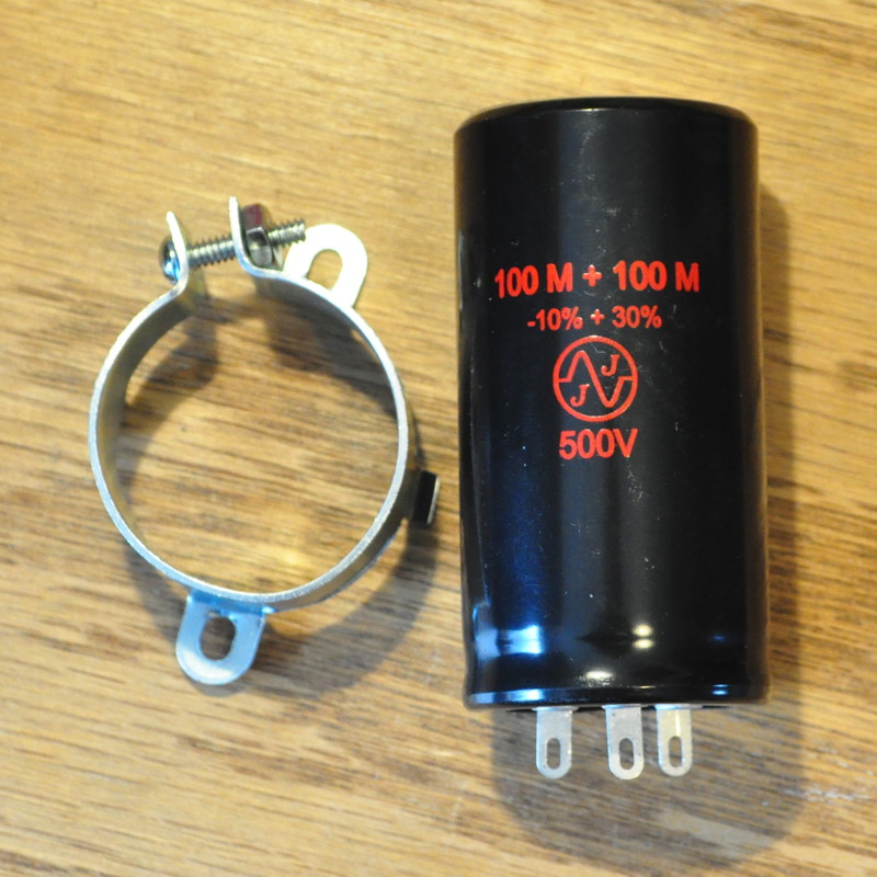 And if I were to build this design again, I probably would. So go ahead and use the bigger capacitor for the driver filter.
And by the way, I know that there are lots of places on the internet where people say that the 807 is the same as the 6L6 but it’s not. They are far different tubes. If you are going to use the 807 you need to pick an operating point and plate load value that really makes sense for that tube.
Thank you for the reply. I’ll use the 100uF in the driver section. Trying to build this a compact as possible given its intended location. Definitely looking in to the 807 usage. Have finalized my plans yet.
Thanks Matt. I’ve been listening to it for a few weeks now. Love it!
Hi Matt,
I hope that you are doing well.
I liked my first build of your 6L6GC UL-SE design so much https://www.diyaudioprojects.com/Forum/viewtopic.php?f=9&t=7336 that I decided to build a second one to use with my main TV in my living room. The amp performs just like the first one – excellent!
The only changes I made were in the power supply. For the power transformer, I used an Edcor XPWR015 (650 V CT @ 180 ma, 6.3 V and 12.6 VAC) instead of the XPWR008 that I used in the first build (600 V CT @ 200 ma). I did this because I used the Triad C-14X main choke instead of the Hammond 193H 150 ohm series resistance instead of the Hammond’s 65 ohms. The first amp’s B+ was 393 V. This amp is running at 417 V or so. Other voltages are as follows:
B+ to driver – 362 V
Driver K to Gnd – 3 V
Driver P to K – 233 V
6L6 K to gnd 32 V
6L6 P to K 375 V
6.3 V heater 6.2 VAC
12 .6 V heater 12.8 VAC
AC Mains 122.8 VAC at time of tests
My thought is that the additional B+ above your design values probably wouldn’t cause any problems, but I’d like your take on it. I’ve been playing the amp for two full days now with no sign of stress. What are your thoughts?
Sorry for the long post and thanks again for the excellent design!
All your voltages look perfectly acceptable. The B+ at 417v is only 4.2% above target. And the plate voltage is only 7% above target. I estimate your plate dissipation is only around 24W so you have lots of margin. I would expect those 6L6 tubes to last a good long time at these operating points. The driver operating point looks close to spot on as well.
Glad you’re enjoying your second build of this design. I really love mine as well.
Hi Matt,
I really enjoyed your study and it helped a lot for choosing plate voltage. About the construction photo I noticed you have chained hater connections and also for B+ same. does star topology helps for hum? Also I have heard about separation of power and signal on sides of mounting plate. would you please advise your experience.
Regards,
Amir
In general, star configurations are no more quiet than daisy chain configurations. The heater connections are twisted pair to minimize magnetic coupling. At 6.3v electrostatic coupling in the heater circuit is not an issue. The high voltage is not daisy chained. There is a common LC filter stage and then each supply filter (2 for the power stages and one for the signal stages) taps off the output of the common filter. This minimizes power supply coupling between power stages and the signal stages.
As for separating power and signals with metal, this depends on signal levels and layout. I used to always have a metal plate between the power and signal sections (like this). However, I have subsequently learned that this is not required except in very particular circumstances.
Matt, I have built a few 6L6 in the past from your schematic. I currently have 10W 3.5K OPTs. Can I use these instead of 5K primary OPTs?
Love the 6L6s I’ve built in the past.
The short answer is yes. But I believe that the bias point would need adjustment. This amp’s power stage design in based on the 6L6 UL optimization study results. This study was conducted with a 5kΩ load value. The results of using this design with the lower load will not be as good.
Hi Matt, I would like to build your amp using parts I have on hand. Namely, an edcor xpwr033-760v xfmr, edcor cxse25-5k opt xfmrs, 6sn7 and 6550 tubes, and two 5h chokes. First of all, any problems replacing the 2h chokes with 5 h? Using dropping resistors what would the ideal b+ settings for power and signal stages be? If I get close to voltages are there any other component adjustments to make?
There are no problems with replacing the 2H chokes with 5H ones. This will improve channel separation. However, the use of the XPWR033 will likely require some redesign of the power supply. That transformer will give a no load rectified voltage of ≈537vdc. and given that Edcor transformers are voltage rated at load it would likely be 40 to 50v higher. This means that the power supply filter caps need to be rated for at least 600Vdc. Otherwise, a blown (or non-functioinal) power tube could cause you to blow filter capacitors in the power supply. This is not a good design.
I recommend using Kemet ALC70 series capacitors for the secondary power supply filters. I’d use the ALC70A101CC630 in the 100µf positions. And I think I’d use the Vishay/Sprague TVA ATOM series part number TVA1966-E3 20µf 630V capacitor in the primary filter position directly after the rectifier. The total load is upwards of 155mA for the bigger tubes so the power rating of Rd must be chosen appropriately. My guess is that Rd will need to drop about 60v at load which is about 60v/155mA≈390Ω at a power rating of about 9.3W. I’d use at least a 15W resistor for margin.
I’m thinking of building this amp, what is the measurements of the metal plate that all of the parts are mounted on?
The top plate is 14″ wide and 10″ deep front to back.
I’m curious about your thoughts on placing the volume control prior to the first stage. Would there be an advantage to placing it after the first stage? Disadvantage? Gorgeous build all around. Well done.
There are only two reasons for NOT placing the volume control in front of the first stage.
The first is if the input signal is very low and I’m worried about noise. Then the first amplifier is placed before the control to minimize Noise Figure and control noise. This is the way a lot of guitar amplifiers are built due to the small signal from electric guitars. Since this amp deals with line level input signals, this really isn’t an issue in this case.
The second is if I want to use the first stage to “color” the sound in some way. A good example of this approach is the 12AU7 “Color” Preamp. Since in triode amplifiers, even harmonics are roughly proportional to drive level, to get appropriate “color” the signal should be of reasonably constant voltage. This dictates putting the control after the first stage. In this topology (i.e. SE-UL) I was going for a more neutral (or “true”) presentation, so I put the volume control first.
I hope this makes my thinking on the matter more clear.
Matt, I have a power transformer salvaged from an rca 183 amp with the following specs: primary 117vac 1.65amp, sec1-640vct@240ma, sec2-5v@3a sec3-6.3vct@4.1a, sec4-6.3v@4.2a. Also have the accompaning choke, 240ma 60ohm dc resistance, 4.3henry.
Do you see any reason this would not be exceptable as the power supply transformer and choke. It would be a substantial cost savings and give me the opportunity to make use of this nice trans. I would love to build this amp. I have built 2 Marblewood amps and 1 Lacewood amp. This would be a great addition.
This power transformer should be acceptable. However, your B+ voltage will likely be even lower than mine was. Probably in the neighborhood of 370VDC. I would strongly recommend that you reduce the power stage cathode bias resistors to 400Ω, 5W. This will increase the bias current a little bit and get you back to toward the optimization curve at the lower B+. I would use these, RS005400R0FE12, for the power stage cathode bias. These are a good quality Vishay/Dale 1% wire wound power resistor.
Let me know how your build goes.
Hi Matt,
Your amp looks great! In the months that I have been listening to mine, I continue to be impressed. As it is used for my computer sound, I had been just using freebie sources from the internet. I decided to subscribe to Amazon Music Unlimited, which has available a vast selection of CD-quality or better music. The improved source really lets this amp shine! I was just listening to a variety of Christmas music. As you mentioned in your write-up, being able to pick out the individual instruments, and the vocal presence. Despite the fact that the speakers are only about 24-inches apart on my desk, the channel separation and soundstage is truly impressive. I never realized that splitting the B+ and using a separate LC filter for each channel could make such a dramatic difference. For the investment in a couple of $10 Triad chokes and a two-section JJ can capacitor, I believe that the improvement in sound is monumental!
Thanks again for the great design work. Wishing you and your family a Happy Holidays!
Jim
Jim; Thanks for your kind words. I have been enjoying this amp as well. I started using split power supples a while back (I can’t really remember when specifically) and my thoughts on power supply design have been evolving. Now I am using fully separated left and right power filters for virtually all my designs. My impressions are the same as yours: great depth of sound stage and an almost 3D presentation to the music. Even vinyl seems to benefit from this design philosophy.
Merry Christmas and Happy Holidays to you and yours.
hello Matt:
Lovely amp.
I am calling from Canada. Up here we lean toward Hammond transformers. Would the 1628sea be the correct output choice, with a 272dx for the power tranny, and a pair of 154m chokes.
I have been reading your articles and am most impressed. Good work and thank you very much.
Scott, I’m glad you’ve enjoyed the site.
The 1628SEA (5kΩ primary, 40% UL-Tap, 120mA Max) will make a fine output transformer for this amplifier. The higher primary inductance from the Edcors will have some minor effects on performance; but nothing about which to concern yourself. The 272DX however is too low a secondary voltage (600v-CT) to reliability get to 400v B+. For this amp I recommend the Hammond 273BX (700v-CT @ 201mA, 5VAC @ 3A, 6.3VAC @ 5A). I would also try using a 5U4GB rectifier in place of the GZ34 for the slightly higher voltage drop. Of course the 154Ms are just what I used.
Let me know how your project progresses.
It’s a beautiful looking amp. I’m sure it sounds as good as it looks. As much as I’d like to build this amp I probably won’t. What with the strong dollar and the weak euro, the transport costs to Spain and import duty, the output transformers end up being just too expensive. I still have one set of 10W Edcors, but from your test results it sounds like they wouldn’t be up to the job in this amp. I also enjoyed the blogging on this project. Very detailed…. lots of info and photos.
The 10W Edcor GXSE are ok for this amp. The performance with the GXSE10 transformers will be similar, just not quite as strong on the low end. Maybe a couple of dB lower at 20Hz. It would still have the quickness and tonal control of the this amplifier. It may even be a small amount faster. You could even still use the KT88s although it might give a slightly lower “peak clean” power level with these tubes.
That’s made my mind up. I’ll start looking for a Hammond power transformer. They’re relatively easy to find here in Spain. The multiple primaries also help me to get the correct voltages.