
“Peck”. This is a term with which I don’t expect most tube amp builders to be highly familiar. However, it is a term that is exceedingly important to my work this morning on the 6AS7 SET amplifier. Let me explain.
To “peck” or “peck drilling” is a machinist term meaning to repeatedly back off a bit or tool to clear chips or allow lubricant/coolant to flow into a hole. To a machinist, especially one programming a CNC machine, it has a very specific meaning. There are also many different approaches to “pecking” and rules for how it’s done dependent on material, lubricant, coolant, tool size, tool type, tool grind, etc.
Now for the record let me state that I am NOT a machinist. I have never operated a metal lathe or milling machine. My metal work is limited to simple cutting, drilling, and filing. And I usually manage to do a rather poor job at that. So when I say “peck” I use the term in the simplest way possible. I only mean repeatedly backing out a cutting tool in the course of drilling a hole. And that’s what I spent the whole morning doing today.
The object of the morning machinations was a 10″x12″ (254mm x 305mm) sheet of Copper 110 alloy, 0 temper, 0.0625″ (1.6mm) thick. This is essentially pure copper (99.9%) with no tempering or heat treating of any kind. For the record it is soft, gummy, and for the amateur metal worker like me, very difficult with which to work. So, like any good Engineer, I’ve developed a process.
When I drill hols in sheet metal for my amps I like to use the two-flute step drills commonly available today. I have a bunch of these drills that have different diameter ranges and step thicknesses for dealing with a number of different jobs. The ones I like are HSS and have a titainum-nitride coating. They look like this.
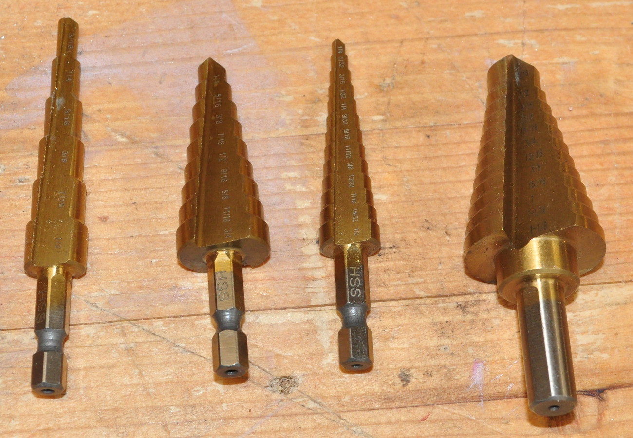
These cutters work well in softer metals like aluminum and copper, however they can be tricky to use effectively.
The problem with using these in softer metals is chip formation. The cutting (or chip forming) action actually occurs along the leading edge of the milled grove that is tapered between the flat (i.e. straight”) sections. If everything goes well, chips are formed on both sides of the hole, 180˚ in opposition to each other and forces balance, chips are ejected from the hole as the bit cuts, the bit runs straight and true through the metal, and the hole is nicely formed. But this is rarely the case. In the case of copper and aluminum, if the bits run too fast, or lubricant is insufficient, or the cutting edge gets too hot, well then chips stick to the cutting edges, forces unbalance, holes drift, hole sides are gouged, and the results are pretty terrible. When I first started working with copper these terrible results were what I got most of the time. Then I discovered the three secrets to making them work well; low speed, lubrication, and pecking.
When working with copper, especially pure copper, heat is the mortal enemy in any machining process. When the soft, gummy copper gets hot, chips stick to the tooling and cutters can grab and tear instead of cutting. The first way to limit heat is to slow things down. For holes up to about 3/16″ (≈5mm) I run the cutters at 360 RPM. For any hole larger than that I slow the cutters down to 250 RPM which is as slow as my drill press will go. Even this slow speed can cause real problems with bigger cutters for things like tube sockets. Which leads to secret number two.
Typically when I need a hole in something, I grab a drill and the appropriate bit, put the bit on the mark, and squeeze the trigger. Usually this works out okay, especially if accuracy and refinement are not required. But when it comes to amplifier parts where some level of accuracy and polish are required, I turn to a drill press and most importantly, cutting fluid. When I first worked with copper plate on the 6DJ8 Headphone Amp, I tried all manner of things to lubricate cutters. However, what I found to give the best results on copper was something I already had for working with aluminum, Relton A-9 Aluminum Cutting fluid.
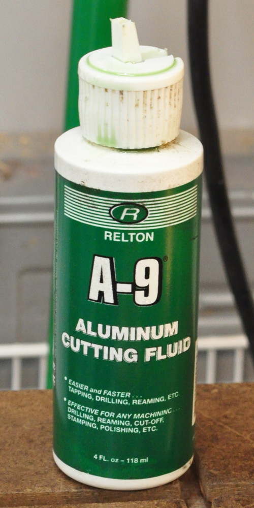
I use this to ease cutting holes in my typical 6061 T-6 aluminum sheet. So I tried it with the copper and it gave excellent results. It smoothed out the cutting process and yielded much better surface finish that anything else I tried. The typical approach to cutting a hole involves painting the cutting tool with A-9 using an acid brush and putting a small pool of the fluid at the center punched location where I want the hole. But there is one more element to getting good results in this metal; the drilling process itself.
This is where pecking comes into play. Now normally, in machinist parlance, the first “peck” or tool insertion into the material is measured in multiples of the cutter diameter. If you have a 1/4″ (6.35mm) bit, then the tool should be pulled back the first time when the hole depth is a multiple (usually 1 to 3) times the tool diameter or somewhere between 1/4″ (6.35mm) and 3/4″ (19mm). But I’m talking about sheet stock that’s only 0.625″ (1.6) thick. The holes are many diameters of the thickness. How can “pecking” even come into play? This is where we have to go back to that simple definition of a “peck”. Recall that the “peck” is for clearing chips (so they don’t mess up the hole) and letting coolant in. To this definition I will add letting the sheet stock (at the hole edge) cool down.
With the machinist definition of pecking comes an assumption that the hole to be drilled is much deeper than the peck (i.e. the material is much thicker than the hole). Through much trial and error what I discovered is that the soft copper acts much differently when being attacked by these step drills. In essence each step of the cutter is in fact a drilling operation. And the cutting angle of these drills is such that they build up an incredible amount of heat very quickly. In addition, under the heat and cutting forces, the soft copper tends to flow in front of the cutting edge, pushing out the bottom of the sheet around the hole. All these factors combined means that any chip which does not perfectly clear the cutter edge and exit the hole can interrupt the cutting and flowing action which is taking place. Because of this it is necessary to clear the chips from the hole very often.
The following image shows the step cutter, chips, and copper plate after drilling a tube socket hole. You can see some residual cutting fluid on the copper sheet and on the cutter.
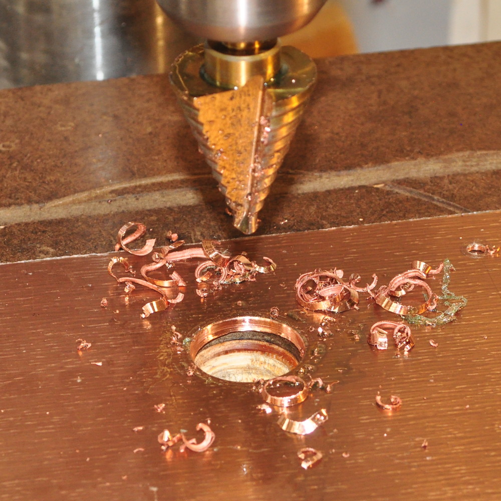
In this image you can see the typical long chips laying around the hole and some much smaller chips clinging to the cutter. The long, ill formed chips are typically what I get when working with copper. Usually they will not shed from the cutter unless the cutter is pulled back from the cutting edge. In this picture you can also see that the apparent thickness of the plate is much greater due to the material which was forced out the bottom of the sheet during the cutting process.
The process I developed for drilling these holes is thus. I usually peck at least twice per each cutting step. The first retraction is performed when the cutting edge is just fully engaged in the material. This clears the smaller chips that form when only part of the cutter is engaging the material. The second peck is then right after the cutter breaks through the bottom of the material to clear the long chips before the next cutter (i.e. step) engages the material. Some times, especially with larger holes like the one shown in the picture there are additional tool retractions whenever I see chips clinging to the cutter longer than about 1/3″ (10mm). On larger holes I also stop drilling every few steps to clear chips from the cutter and around the hold and to apply additional cutting fluid. When the hole is the correct diameter, I clear all the chips, flip the sheet over, and use the cutter to deburr the hole on the back side.
This may seem like a rather messy and tedious process; and it is. In addition, the torque on the copper sheet when drilling large holes can be significant. For these holes I usually firmly secure the plate to the drill press table when making the hole. This securing also helps prevent the hole drifting off center if the two flutes cut at differing rates due to a bonded chip.
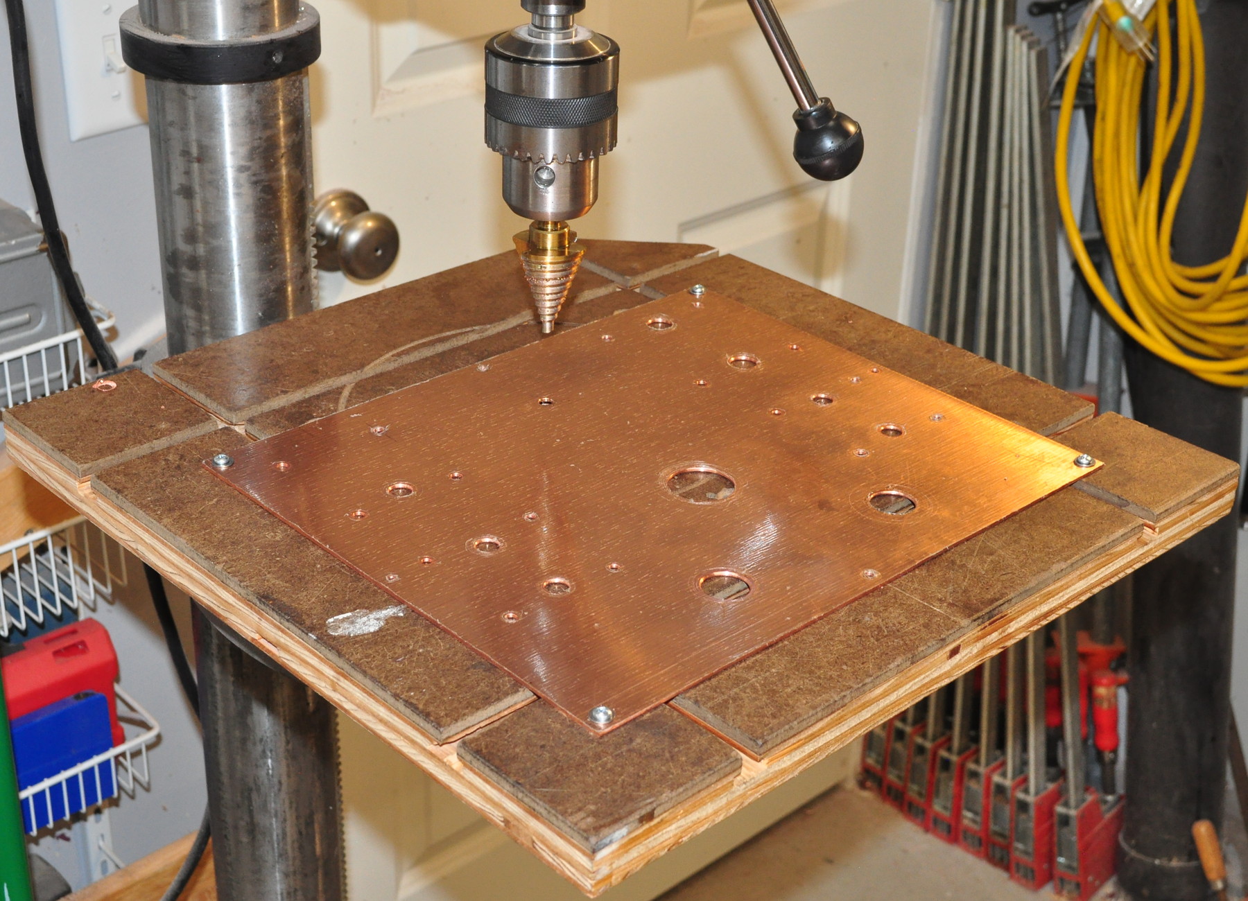
The following image shows the top plate secured to the drill press table with screws before drilling the hole for the rectifier socket. I’ve found that just clamping can fail on the large holes due to the very high cutting torque and the slippery layer of cutting fluid that seems to get everywhere while I’m working.
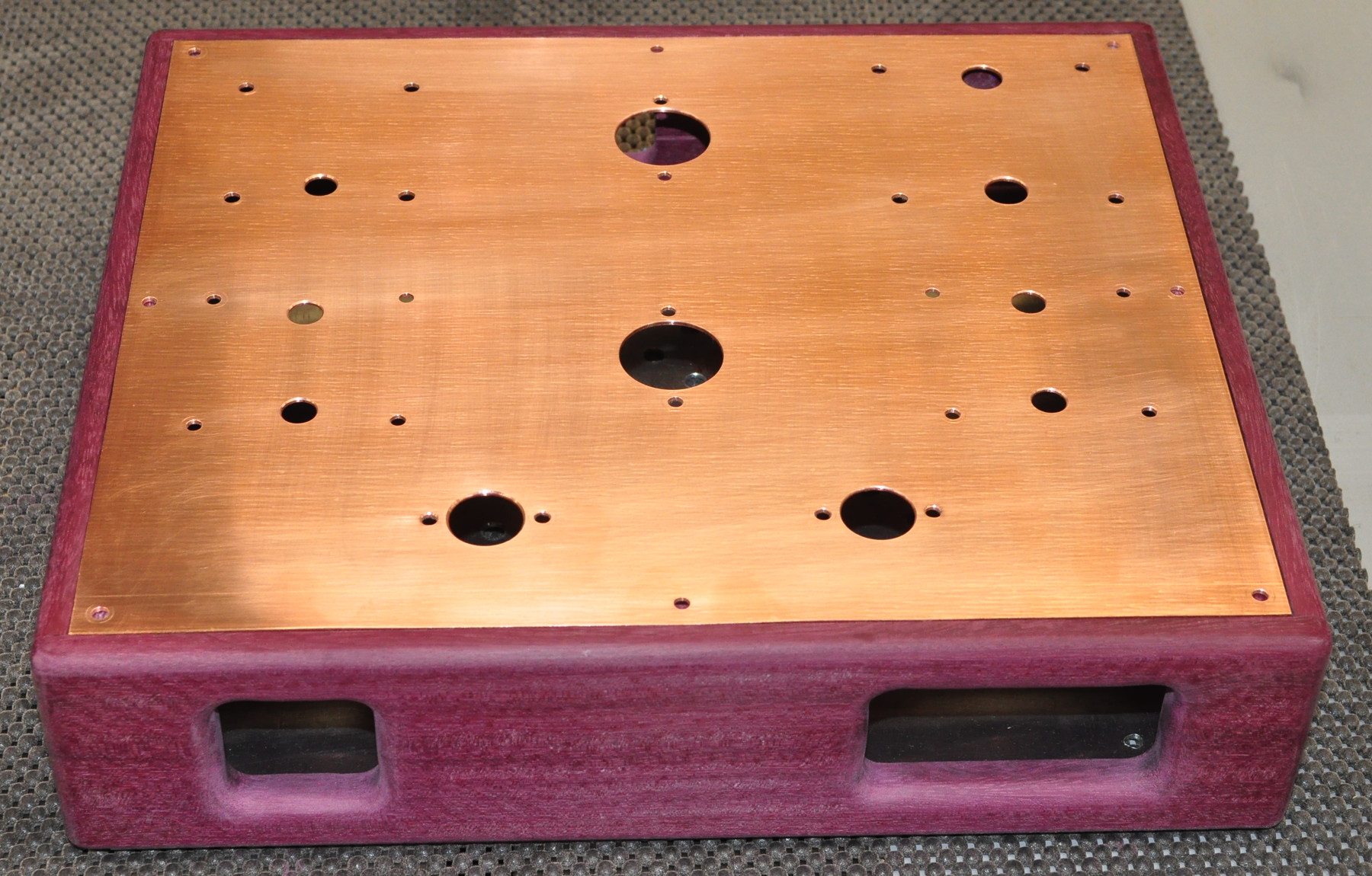
This entire process took all morning to complete the top plate for the amp. However, I think the results were well worth all the effort. I took the plate back to my work area and test fit all the transformers and sockets. All the holes lined up perfectly. Here is the final result of today’s work.
Now that I’m done playing with the metal formation I need to complete the sanding on the chassis and start applying an oil finish to the wood. I also need to start experimenting with the copper to get that nice patina for which I looking.
Let me know what you think so far. Comments and questions are always welcome.
The metal top looks great and has a nice contrast to the wood sides. The cutting fluid seems to be a good solution. I have seen people use all sorts of things, even bar soap, to try and keep soft metal from clogging up cutting teeth. I enjoy hearing you think through the problem with a methodical approach, and I am looking forward to the reading about your patina process.
Thanks Matt for passing on the benefit of your experience on this important step. I might have done a better job on the Hammond enclosure for the 300b amp had I followed your technique. No excuse next time. How do you approach hole positioning for the transformers, choke and tube base holders? I pencil marked the hole locations from the mounting points of the transformer, choke and tube base holder, and judged where the wire loom holes should go. That approach was not entirely satisfactory. I used a hand held drill too which also contributed to inaccuracy.
In addition to my normal layout tools (discussed here) there are two addition things I use to help achieve an accurate layout. The first is an ultra fine point “Sharpie” marking pen. I do the layout based on detailed measurements and use layout lines marked directly on the metal.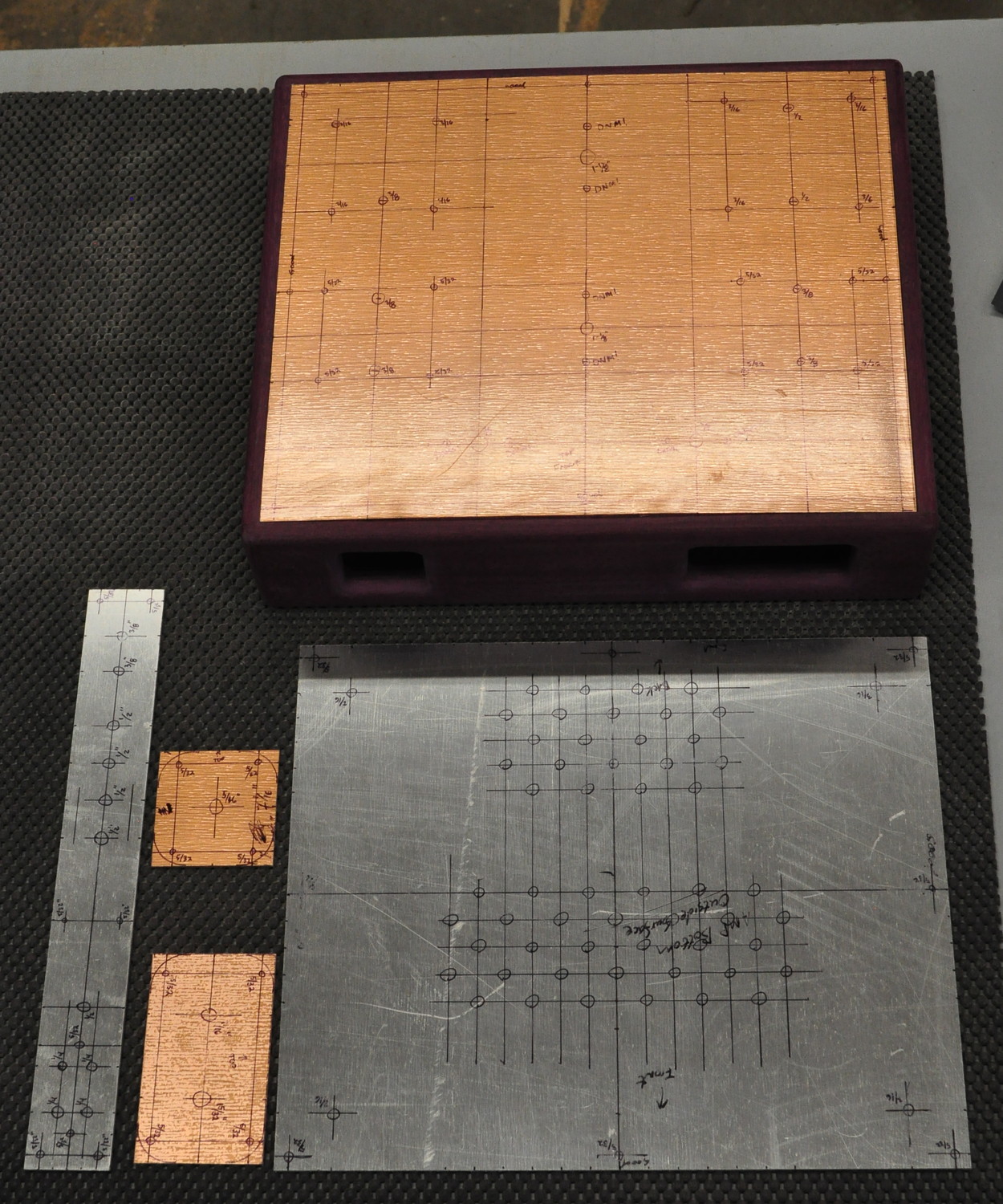 This type of marker is a nice tradeoff between line width and visibility. The other secret is a simple automatic center punch. With the metal laid on a hard surface, it is a simple matter to precisely set the punch and a simple push leaves a nice little divot to start a drill. I never drill a hole without first using a center punch to mark the location. It just makes drilling way more accurate.
Another approach if you have access to an A3 laser is to draw in software, print at scale, glue to your board and punch.
A centering drill bit helps to be more precise as well.
Excellent work and advise Matt. I learned machining 40 years ago and yes, aluminium and especially copper tend to stick to tools. This is probably why commercial product use metal sheets cut by laser and powder coated. Much cheaper than what you do, less nice and so boring. Keep on !