
I keep getting questions about amp grounding so I thought I would consolidate some of my previous notes on the subject. The first is a reprint of a forum post I made back in 2013 on the DIYAudioProjects Forum.
Warning: It has been brought to my attention that some people reading this post mistakenly believe that I am advocating the override, disconnection, or elimination of the safety ground (or bonding) connection in some pieces of equipment. This is not correct! The safety ground or bonding requirement for every piece of equipment is a firm requirement. At no time should any signal cable or independent wire be expected to fulfill the safety ground requirement for any piece of equipment. The process of “ground lift” is simply to provide a different signal ground reference in a piece of equipment.
When it comes to grounds, I am of the opinion that most people simply do NOT pay close enough attention. It is really not enough to simply look at a piece of equipment and try to decide on the ground scheme, you really need a “system grounding philosophy” that applies not only to equipment you build, but everything you use. The thing about the fight between the “direct ground” camp and the “parallel cap/resistor camp” is that the actual grounding philosophy is never discussed. The cap and resistor separation between chassis and signal grounds was almost an absolute requirement with two wire ac systems to achieve a safe design. Today it, more often that not, leads to funny ground loops and background noise.
So, what do I mean by a “system grounding philosophy”? This means that the grounds in your system must be managed to both provide safety and to avoid ground loops and currents. This is not as simple as it sounds at first. And it depends on how your equipment is constructed, how it’s grounded, and how it’s interconnected. It also depends on the type and quality of your power system where the equipment is used. Everyone who has a system should have a ground plan to manage noise and safety. It just makes good sense when connecting multiple disparate pieces of equipment; be they audio equipment, radio gear, or test gear.
Let’s look at an example; me. I have a good quality three wire power system with excellent ground path impedance. I have checked ALL my outlets for proper hot/neutral wiring and impedance to ground spike (not a simple task). Given this, I have developed a grounding philosophy for all my equipment. Here it is:
Matt’s Audio System “System Grounding Philosophy”
1. All separate pieces of equipment shall use IEC-53 connectors and implement independent 3rd wire safety ground design.
2. Chassis grounds for all pieces of equipment shall be provided by that piece of equipment’s safety ground lead. The IEC ground lead shall connect to the main chassis and all exposed metal parts, except for signal/speaker connectors, with a DC impedance not to exceed 2mΩ.
3. System wide signal (and speaker when used) ground reference shall be provided by the system power amplifier.
4. Power amp signal and chassis grounds shall be tied together at only one point, this point shall be within the chassis, and this connection shall have a DC impedance not to exceed 2mΩ.
5. No preamp, equalizer, switch, control, or other equipment shall connect signal ground to chassis safety ground except through a “ground lift switch” which can break ground connection when used in-system.
6. Signal ground reference for equipment other than power amps shall be provided via interconnect shields or separate ground wire connection (e.g. turntables with magnetic cartridges).
7. When multiple signal grounds, via cable shields or ground wires, connect two pieces of equipment, those cables and wires shall be bundled in close proximity to each other to minimize field coupling area.
8. At no time shall signals pass between system components without signal return paths (either shields or conductors in twisted pairs) for each signal connection.
9. Existing two wire commercial components used within the system shall meet these requirements, utilize an isolation transformer to supply AC power, or be connected to the system using a line level isolator on all signal lines.
Now this is my grounding philosophy. I do not mean to suggest that everyone should follow these rules. Everyone should apply rules that are appropriate to their situation. However, I will tell you that my system, regardless of how I configure it, is a silent as death itself with no signal input. And every piece of my equipment has a safety path for fault currents that will not run through anyone touching a chassis or control. This is the way I like it.
So what does this mean to you? The answer is: “it depends”. If like me, you have a good quality three wire ground system, you may want to adopt a philosophy like mine. But maybe not. You will notice that this ground philosophy tends to drive you to always use either a power transformer or an isolated switching supply in each piece of equipment (except the power amp, however it’s a good idea there as well).
Now this pretty much sums up my entire amplifier grounding philosophy. The one point not addressed is the concept of the “ground lift switch” and how this should function as part of a well designed and grounded system. The following is the repeat of another forum post back in 2014 explaining the concept and usage of the ground lift switch.
There appears to be some confusion concerning the ground lift switch implemented in this design. So I thought it might be good to go over a simple review and explain exactly why this switch is important in modern equipment.
Traditionally there has not been a need for a “ground lift” capability in audio gear except in a few specific situations with professional equipment. The primary reason for this has to due with the evolution of modern power systems and modern design. Traditionally, most electrical wiring systems were two wire and contained no inherent ground reference. In some 120vac systems the “neutral” lead was connected to earth ground at the power panel but not always. This philosophy of power distribution (as well as the need for voltage translation) led to the widespread use of power transformers for system isolation. In this way the power leads for the equipment could be electrically isolated from the electronics (from a ground reference perspective) and the AC power could be supplied via the traditional two wire interface.
The figure below shows a simple signal/preamplifier/amplifier system wired with this traditional philosophy.
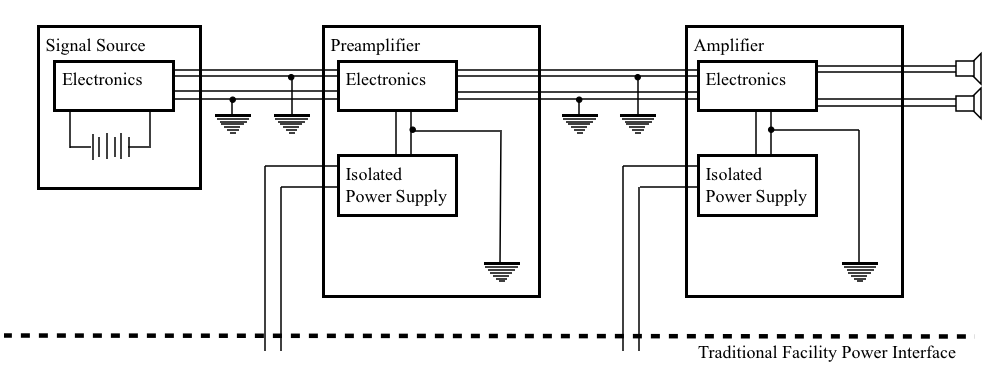
In this situation, each unit has a collective ground which is isolated from the facility power system. This prevents the generation of any large ground loops via the facility power system. This is important because a ground loop will inject signal signals into the audio chain by coupling stray electromagnetic fields from other equipment in the environment. And the strength of these signals will be proportional to the area of the ground loop. In the above setup the signal ground reference is provided entirely by the interconnect cables and everything works out alright.
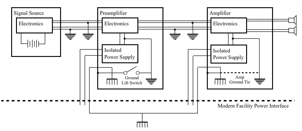
In modern systems things are not quite so simple. Modern wiring system are typically three wire systems with one wire dedicated as a safety ground. In addition in polarized systems, one wire is dedicated as “hot” and the other as “neutral”. Slowly but surely most power systems worldwide are moving toward these polarized, three wire standards. This is a good thing for both safety and compatibility, but it does generate some complications for those of us building new equipment.
Below is a figure like the one above, but modified for the polarized three wire standard. I have included in this diagram, both a dedicated amp ground path and a preamp ground lift switch.
In this case, there are four possible conditions under which the system may operate. Lets start with the amplifier. There are some situations under which two wire power cords are still allowed. These conditions have to do with the chassis construction methods and the isolation of voltages preventing them from coming into contact with the chassis (and hence people). So the amplifier in our system above, may have a ground tie between it’s respective grounds, or it may not (it may or may not have a facility safety ground at all). This uncertainty is were the trouble begins. Because we do not know the ground state of the amp (or because it may change as we change equipment), we need to be able to adjust to whatever the situation may be. Below is a table showing the possible permutations.
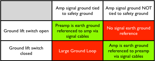
The two green conditions assure that fault currents are properly grounded (good safety) and that the signals path has no ground loops (good fidelity). The upper right hand red condition has no earth path for fault currents (bad safety) but consistent single flow signal ground path (good fidelity). The lower left hand red condition has ample earth paths for ground currents (good safety) but large ground loops contributing to the signal path (questionable or poor fidelity).
So there is the purpose of the ground lift switch on the preamp. By properly setting the switch, depending on the system, it allows us to maintain both good safety and good fidelity.
So, between these two posts, the reader should get a good introduction to my grounding philosophy.
As always, questions and or comments are more than welcome.
2. “Chassis grounds for all pieces of equipment shall be provided by that piece of equipment’s safety ground lead. The IEC ground lead shall connect to the main chassis and all exposed metal parts, except for signal/speaker connectors, with a DC impedance not to exceed 2mΩ”.
Thanks for the article Matt. Am I reading this wrong? Does this mean that I should use isolated RCA sockets for signal in?
I always use isolated RCA jacks; for both signal inputs and outputs. This allows me to control the grounding scheme at the interfaces to the equipment.
You can use non-isolated jacks, however (in my grounding scheme) this means that the signal to chassis ground tie is at the signal inputs. Like most design choices, it’s a trade off. I prefer the flexibility that isolated RCA jacks provide.