
For those that are paying particular attention to my amp builds it will come as no surprise that I think the #44 and #47 (0.9 and 0.5 candela respectively) indicator lamps are a little bright to be used on tube amps. I just think that they tend to overpower the look of the amplifier when the room gets dim. However, as these lamps are ubiquitous, it pays to use them in our builds. So, on the 6DJ8 Headphone amp and the 6EM7 vertical amp I included a small adjustment potentiometer to tame these power indicators. And on the Marblewood amp, I chose a fixed 25Ω 1W resistor to dim the indicator.
However, as I was contemplating a new amplifier design, I was considering using a couple of these lamps to provide a backlight to a chamber holding the tubes. So I wanted to be able to play with different lenses or jewels, and different bulbs. And I wanted to be able to vary the intensity. Clearly I would need something a little more than some alligator clip leads and sockets. My answer was to throw together this little jig.
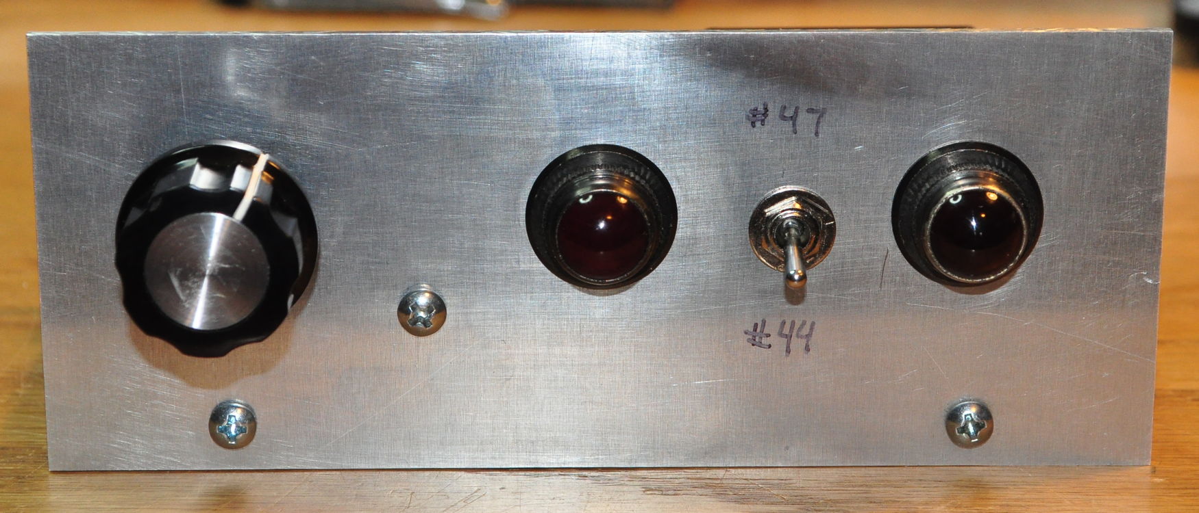
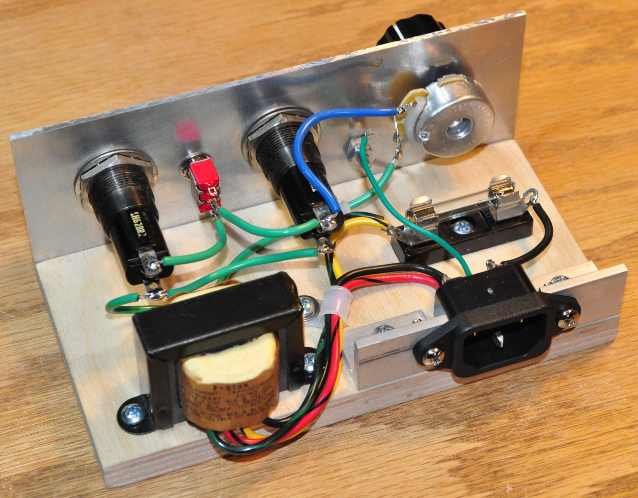
As can be seen this is a fairly simple jig. It’s just a piece of aluminum plate and a small base of baltic birch plywood with parts attached. It contains a couple of indicator panel sockets, a rheostat to vary the intensity of the lamps, a switch that selects one or two sockets, and a minimalist power supply. There isn’t even a dedicated power switch, just plug it in and it’s on. This was built entirely from parts I had on hand.
Some people may question the wisdom of spending the time and money to build something like this. It seems to be fairly single purpose, and these are parts that could have been used in another project. And then there is the cost. However I should mention that the most expensive item here is the 50Ω, 5W rheostat. The panel indicators were bought from a used electronics place for 25¢ a piece, the little filament transformer was $1 from the same place. The other parts are all part of bulk buys for significantly less that $1 each. Overall I think I have about $10 USD into this jig and about 90 minutes of my time.
The real benefit of this device is that it allows me to focus on what I want to do (i.e. investigate various light arrangements) and takes away the tedium and problems associated with the “how” to do it (i.e. the power supply, light sockets, electrical connections, etc.). I really don’t know how often I’ll use it, but it will always be available if I want to check some bulbs or just see what a particular jewel or lens looks like in front of a bulb.
So does anyone else build jigs like this or am I a misfit among the masses?
When I built my last 6V6 in an old Marconiphone bakelite case, I had to fix the indicator lamp lens to the case, with the lamp itself floating in mid air, in a hole on the front of the new chassis. This enabled me to pull the chassis out easily when and if I needed to. As an unexpected bonus it allowed me to move the lamp closer or further away from the lens. After a couple of attempts I managed to get a nice glow that wasn’t too strong when the lights were low.
The next thing I want to do with this enclosed amp is to put some lighting in the case itself.
I think your jig, modified so that the lamps are on small extension leads separate from the jig, would allow me to move them around in the case and choose an appropriate resistor if they need taming down. I shall probably build it next weekend (back at work today after eight week lockdown).
Yes, you are a misfit among the masses, but don’t change.
Matt,
I think that your jig is a great idea. In the future when you are looking at various lighting options this will save you time. You have added a very useful tool to your tool box. One of the things I enjoy about your builds is that you pay as much attention to the overall look, as you do to the sound quality. Your approach turns amps into art. I currently don’t have any jigs, but am considering investing some time into building a flexible input device. I have included a link to an article you might find interesting http://www.firstwatt.com/pdf/art_h2_v1.pdf
In my case, I would probably not build a jig for testing pilot light appearance.
I’ve tested many LED pilot lights on the bench, gotten what I thought was a suitable brightness, but later found them to not be what I want when installed in the control panel. If you are going for “looks”, I think the only way to select the brightness is by installing the light in its “home” and tuning the brightness there. That way you get to see exactly how it looks in the place it is goin to be used.
LED’s always seem a lot dimmer out in the open, then blind you once installed in the front panel.
Frankly that’s one of the reasons that I included a potentiometer in the 6DJ8 HP amp and in the 6EM7 Vertical amp. I got away with the fixed resistor in the Marblewood only because I had played with the other two amps and their dimmers. But running multiple dial lights for illumination, I just had to get an idea of how that might work.
So you’re a firm ‘no’ on this particular jig. Do you ever build other electronic jigs maybe along a different vein?
On the hobby electronics side – no,
I don’t do anything terribly complex
On my professional industrial electronics side – too many to count, have to be able to quickly perform documentable, repeatable test and adjustment of systems and subsystems.
The best one consists of a PLC and HMI terminal. I have developed many different programs for this setup to be able to test and adjust all sorts of industrial control systems. Basically, this jig is used to simulate the machinery the control system runs.