
The arrival of the output transformers today gave me the impetus to finalize a few things in the 6AS7 SET design. So now I have a complete schematic with all the important information noted on it.
Here is the schematic for a single channel of the amplifier and the whole power supply.
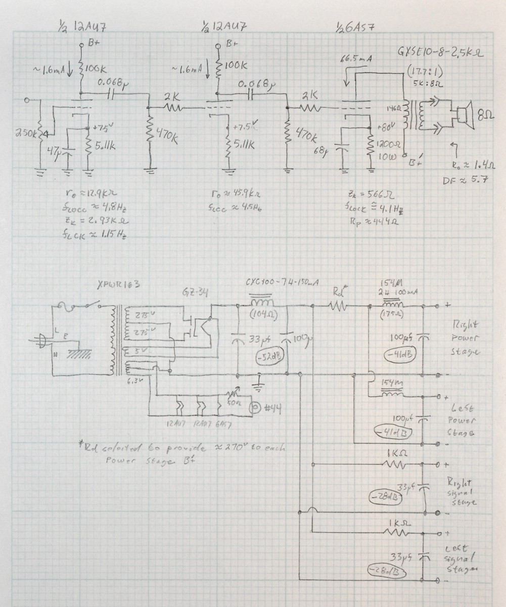
A few things of note. First is the fact that only the first stage of the driver is cathode bypassed; and its bypass capacitor is rather large. I have done this to keep the low end response as full as possible. This is ok because power stage will overload long before this stage ever comes close. In fact, even in major overdrive situations, it is unlikely that the first stage of the driver will ever be overdriven.
Second, the damping factor of this amp is in the neighborhood of 4.2 meaning that it should handle some of the larger, high efficiency speakers rather well. Better than the zero-feedback UL amps and much better than any pentode amplifier without major feedback. (I know it says 5.7 on the schematic but I forgot to include the output transformer primary resistance when I wrote that. With that extra 146Ω the output referenced output resistance is closer to 1.9Ω instead of 1.4Ω)
Third, the B+ supply to the signal stage filters is BEFORE the dropping resistor in the power supply. This is because the power stage need to run off of ≈270v but the driver B+ to be as close to 300v as possible to get the full driver swing at relatively low distortion. This also means that this is not one of those amps where you can adjust the B+ by choosing a different rectifier tube with a different drop. This design is purpose built for the GZ-34/5AR4 octal rectifier.
Lastly, I’ve been told that the way I draw the power supply with negative reference terminals for each voltage confuses some people. This lines are for reference only and don’t correspond to actual wires in the design. I may change the way I draw supplies with each voltage referenced instead to the signal ground to avoid confusion. I’ll think about that when I post the final project page.
The next step is final hardwood selection for the chassis and some time in the shop to get it put together. More to come.
Matt
I bought the small chokes some time back based on your design for Paul (the Hoj). I have the Hammond 156R 1.5H 200mA. Will these work ok in the circuit instead of the 2H chokes for this build or should I compensate with a larger first choke (I don’t have this yet).
Thanks
John.
The short answer is, yes, they will work fine in the circuit. The 2H/100µf filter sections in the schematic provide ≈41 dB of ripple rejection at 120Hz. Changing the inductor to 1.5H still provides ≈38.5dB.
In this PS design, the post rectifier ripple (before the main inductor) was calculated at -34.4dB. The 7H/100µf main stage filter provides an additional ≈52dB of rejection. For a main filter ripple level of -86.4dB. This means that the power stages with the -38.5dB of rejections will see a ripple level of almost -125dB! This is 35dB margin over design target. Another major benefit of the chokes is major suppression of any higher frequency noise which may make its way into the chassis via mains.
Thanks Matt. Good to know I can use these chokes.
Great to see the project kick off though I’m also following the 6L6 design with interest. Are you able to share the reasoning for the choice of the operating points of the 12au7 and the 6as7?
The operating points for the 12AU7 are specifically to obtain the high output swing to drive the 6AS7 biased to 80v. I discussed this cascaded driver previously here, here, and here.
As for the 6AS7/6080, I chose the 80v point first with the 2.5kΩ based on power and distortion trades. Then I selected a reasonable current level based on available bias resistances. The B+ just falls out of those decisions.
I had originally thought to load the big triode with a 1.7kΩ load but I was never particularly happy with the performance. The 3.5kΩ load just doesn’t produce enough power. So I settled on the 2.5kΩ load as a nice “sweet spot” for the tube.
Thanks much appreciated. I missed that third post above. Looking forward to the build.
Been meaning to ask. In many of your circuits, I see 1% resistor values (12au7 cathodes are 5.11K). Is this due to a “technical reason”, personal preference, or you have a lot of 1 percenters on hand. I could be wrong, but would a 5.1K 5% be just as suitable? Reason I am asking is that 5% resistors are universally available, tighter tolerance ones are less so.
There are a couple of reasons for this. One, I like to use metal film resistors due to their excellent noise characteristics and the suppliers I generally use (Mouser, Allied, Digikey, AES, etc.) supply these resistors for very reasonable prices. Over the years I have amassed quite a collection of 1% metal film resistors. So they are typically what I choose.
I also like the fact that I can precisely pick the values I use. This serves two purposes, first it means that channel to channel performance is only due to tube variation. In zero-feedback amplifiers like I build, this is important. Second, it allows the designs to run the tubes closer to their maximum power loads because the build variability has been reduced. In SETs and SE-UL designs, every little bit helps.
I also like that manufacturers are starting to supply 1% tolerance wire wound power resistors at reasonable prices. This allows me to set power stage cathode bias levels and B+ supplies with much greater precision.
The bottom line is that since I’m only building one of each design, and I want to document the performance of the “design” and not just my build for those looking at the website, I like my builds to be as close to the design point as possible. None of my designs require this level of tolerance, but it is the way I prefer to build.
Yes, I also use metal film resistors, they are of the “flameproof” type, which are typically 5% tolerance.
My basic design philosophy is to mimic commercial design practices. I usually build two or three of the same design, mainly to see if each one has about the same performance – that way I know I have met my goal. Draw, calculate, simulate, grab parts out of the bins, build, works just like the last one.