
I took some time yesterday to perform a performance check on the driver for the 6AS7 SET. As some may recall, this driver was developed and prototyped back in 2015, and brass boarded in 2016, as a driver for the 6336 SET Amplifier. In the 6336 design it uses a 300v B+ to produce a swing of 82V peak to fully drive the big triode. However, in the unique power supply topology of the 6AS7 SET, there are some additional considerations.
A quick check of the 6336 SET power supply schematic will show that the power stage requires a B+ voltage of 360v and the driver section a B+ 300v. So, in the 6336 design, I simply inserted a 20kΩ/33µf RC filter to get down to the required driver voltage. The power supply design for the 6AS7 is somewhat different.
A quick look at the 6AS7 SET power supply schematic will show that I have a different issue. In this amp the power stage requires a B+ of ≈265v and the driver stage requires ≈300v. This means that I have a power supply where I have to design for the driver supply voltage and then use a dropping resistor to get down to the voltage for the power stage. Looking at the schematic shows how I plan to implement this.
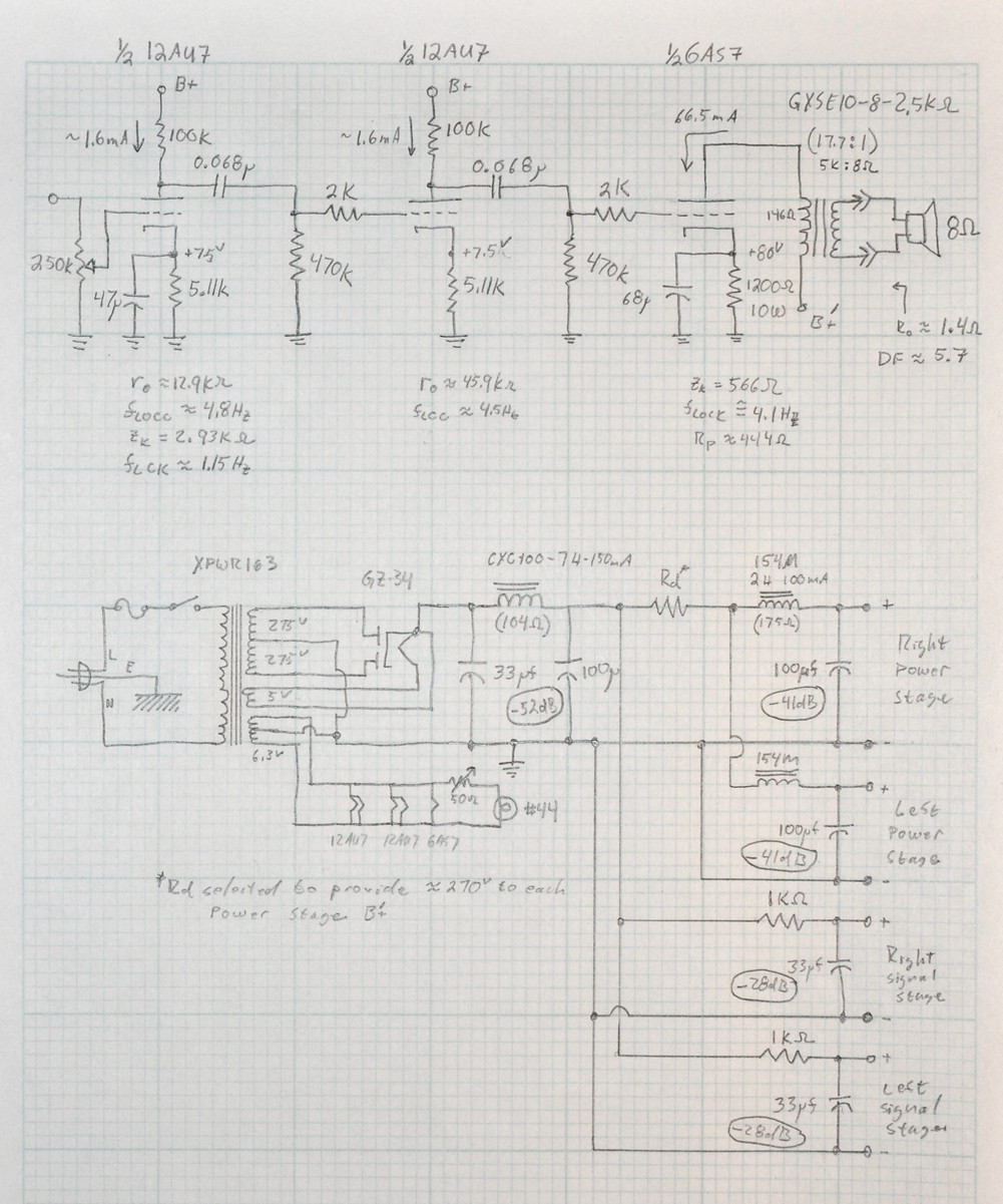
Note that there is no dropping resistor between the primary filter and the driver stage filter. Because the driver stage draws a combined current of ≈3mA, the voltage loss in the driver stage filter should only be about 3v. Now on to the real issue.
In designing the power supply for the amp, my calculations show that the voltage after my first filter is more like 295v. So from the beginning I’m already a little below target. Not much (≈1.7%) but I don’t like starting in negative territory. Here are the numbers from the primary filter design.
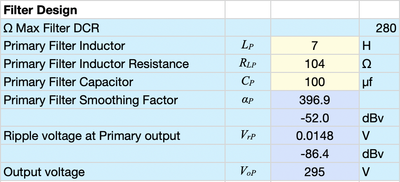
Meaning that my driver stage B+ is now more like 292v instead of 300v (≈ -2.7%). And this assumes that everything works as planned. If the voltage is a little low or my calculations are a little off, it could be even lower. To address this I decided that the first thing I’d do is test the prototype driver and see how it does. I decided to run this test at 275v B+. This is about 8.3% below the B+ design point but I thought it would give me a good idea of how the driver performs in a worst case scenario. Here is how it performed.
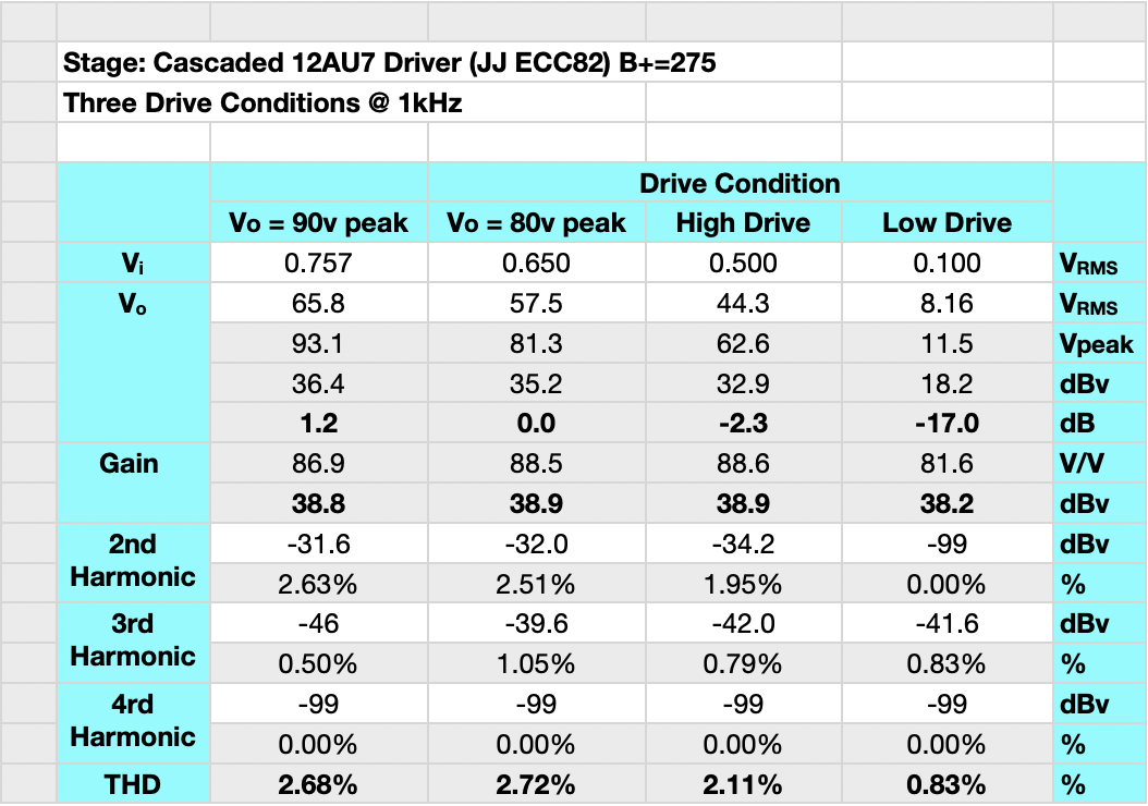
The good news is that the driver went well beyond the power stage bias point and continued to perform. I checked the performance at two representative operating points, at the transition to power stage overdrive (Vo = 80v peak), and 10v above power stage overdrive. All performed well with no indication of excessive compression or clipping. In the overdrive condition the stage started to slip into a slight compression of ≈0.2dB.
This makes me feel much better about this cascaded driver using the power supply I’ve designed. This driver design seems to be proving itself robust and insensitive to variations in operating parameters. Time to get back to work on the amp.
Looking at the driver schematic for the 6336, I see you dropped the first bypass cap to 22 from 47, and you increased the grid resistor from 2K to 5.11 K. Is this related to the B+ factors you mentioned?
There are some slight differences. Most of which are due to my growing familiarity with the driver.
You are correct that for the 6AS7 SET I have increased the first bypass capacitor. This is to improve the low end a little bit. Given that the stage is biased at ≈7.5v, it should be next to impossible to overdrive the input in most cases. As such, I felt somewhat more confident that I could avoid cathode shift in overdrive.
I’ve dropped the grid stopper on the second stage to help the high end. Again, second stage bias recovery shouldn’t be an issue since the power stage will always be the first to go into conduction by a significant margin. The power stage Miller capacitance is calculated at about 27µµf. With the 2kΩ grid stopper, this puts the high frequency limit of the power stage in excess of 100kHz, This means that the high frequency response of the amplifier should be controlled entirely by the output transformer. This is different from the 6336 where I used a significant grid stopper (probably too large) to control the big triode.