
As I was going through some things today I stumbled upon an email discussion I had recently on the topic of toroids (i.e. toroidally wound transformers and inductors) and shorted turns. Given the popularity of toroids, and amount of misinformation floating around on the internet on the topic of shorted turns, I thought that a short discussion of the phenomenon was in order.
I have seen posts on the internet ranging from those suggesting that this is a non-issue to predictions of flaming arcs and melted transformers if you ever even temporary short the ends of the mounting bolt. As with most things in Engineering the reality is a little more nuanced and complicated.
The first thing I would like to say is that this is a real phenomenon. If someone tells you it’s not, they are wrong. A shorted turn (or for this discussion I’ll use the term “closed path” because I don’t want to get focused on what “shorted” means) will place a load on the magnetic circuit in the core and can seriously affect the operation of the toroid. This is a simple consequence of Ampère’s law. There is no amount of shielding or routing which will change this. It is a simple fact of the basic electromagnetic physics.
However, what constitutes a closed path, and the resultant effects, is far more complicated. I’m going to start with a definition: For a toroidally wound inductor or transformer, a closed path or “shorted turn” is any electrically conductive path which fully encompasses one cross section of the core (i.e. goes through the center and around the outside). Typically this closed path is associated with a “low” electrical resistance. Typical closed path configurations involving toroidally wound transformers or inductors are shown graphically in the following figure.
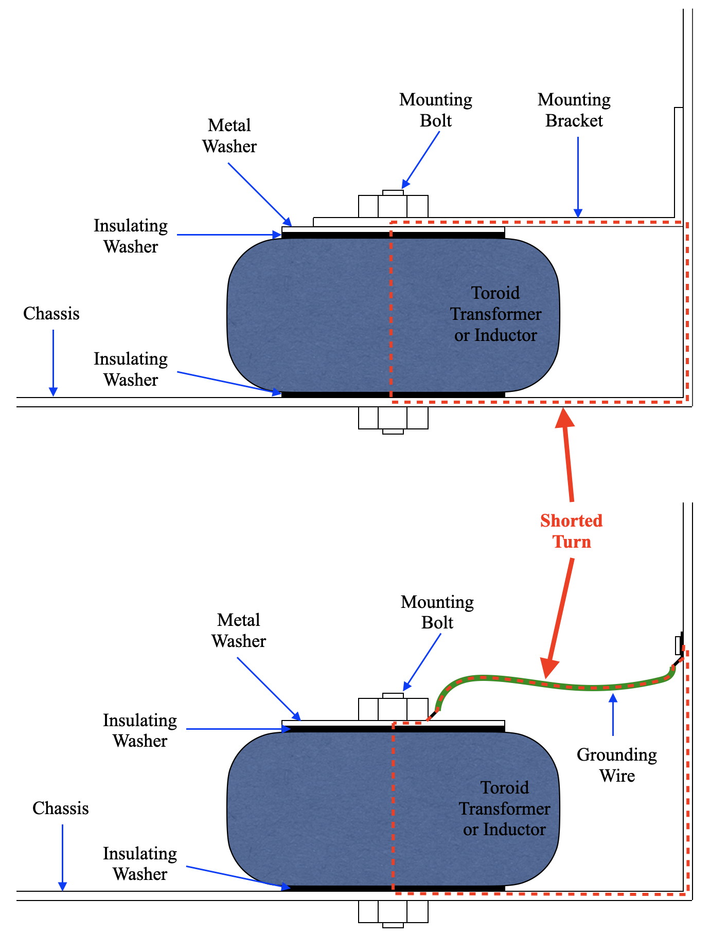
I’ve added the lower figure to illustrate a point. A shorted turn is any conductive path. The wire in the lower figure could run all over inside (or outside) the chassis and the effects would be the same. The closed path simply needs to go around the magnetic flux contained in the core.
However, the effects of a closed path are different depending on the nature of the closed path. I’ll start with a theoretical example: Let’s say you have a power transformer rated at 100VA. This is really a measure of the maximum power the core is able to shift from the primary to secondaries. So if the “closed path” has a resistance of exactly zero (remember that this is “theoretical”), then all the power from the core will go into the closed path and the secondaries will get nothing. The core will saturate and probably dump maybe 30% to 50% more power than rated into the closed path, but it is not assumed that the primary draw will blow a fuse. Output voltages on the other secondaries will be seriously dependent on load and may be anywhere from close to specification to nearly zero.
But let’s look at a more typical, real world, example. Let’s assume that same 100VA transformer specifically with a 240vac primary and a 30vac secondary. Further let’s assume that the secondary has 60 turns (for a nominal 1/2 volt accuracy). Therefore the primary has (240vac/30vac)*60 = 480 turns. Further we will assume a mechanical configuration shown in the figure above. This has a closed path through the center of the toroid. It also has, by my estimation, between three and five mechanical interfaces through which the current needs to pass.
An important fact to know is that it is actually much more difficult to obtain and maintain truly low resistance mechanical bonds (say less than 0.1Ω) than most people believe. In fact, a value of 0.1Ω to 0.5Ω is more typical for most mechanical interfaces which have not been specifically treated for high conductance. For our example I’ll assume 4 mechanical interfaces and 0.2Ω per interface. This means that our “closed path” actually has a resistance of ≈0.8Ω; this is important.
Since this mechanical path is a “single turn”, the turns ratio is 480:1 and the voltage across our mechanical path is 240vac/480 = 500mVac. Further, 500mV across 0.8Ω yields a current of approximately 625mA. This may sound high, but the power going into this closed path is only (I*I)*R or 0.625^2*0.8 ≈ 0.31VA. This is neither a major draw on the 100VA transformer nor is it a large amount of heat to be pumping into the mechanical interfaces. It will not cause fuses to blow or things to get hot. Note however, as the resistance drops you can quickly get into a situation where the draw becomes much larger. At 0.4Ω the current rises to 1.25A and the power rises to ≈0.63VA. And at 0.2Ω the current rises to 2.5A and power to 1.25VA. These are still not catastrophic values from the toroid’s perspective but at these levels the effects on the amplifier can become problematic.
Even without “flaming arcs” and other catastrophic failures this situation can cause some serious issues. And the magnitude of these issues will vary dependent on the nature of the closed path. Here are some of the bigger issues.
Chassis Currents and Mains Noise: The first downside is that this will cause not just the primary current, but eddy currents as well, in the mechanical chassis. The magnetic flux from the these currents are uncontrolled and can couple into all kinds of items (wires, PCBs, components, etc.) in the amplifier. This results in pumping mains frequency noise into the signal components. Depending on where this happens, it can be anywhere from annoying to having catastrophic effects on performance.
Core Magnetic Flux Behavior: The next problem happens in the transformer itself. The low impedance of the closed path can also cause issues with the core flux as it changes at mains frequency. Transformer/inductor core design is a balancing act between size, cost, and performance. The core can be smaller if the winding impedances are greater, but too great an impedance causes secondary losses under load. This “balancing act” is carefully managed to hit all the design points for a minimum cost. A very low impedance closed path upsets the core circuit and, depending on the hysteresis characteristics of the core, can cause issues anywhere from odd frequency behavior in output waveforms to mechanical stresses exceeding design points resulting in buzzing and noisy magnetics.
Transformer Aging and Failure: In all cases the closed path will represent a highly off nominal operating point for the transformer and will result in rapid aging and premature transformer failure. The degree to which this will happen depends on the specifics of the closed path and the transformer in question.
So overall “shorted turns” or “closed paths” around the toroid core are definitely something to avoid. They will always affect the performance of the transformer to some extent and can cause problems from simple main frequency noise, to transformer heating, to catastrophic failure. I hope this helps to clear up some of the major misunderstandings concerning the installation and usage of toroids in amplifiers.
As always, questions and comments are welcome.
Pingback: Other Projects and Updates | Cascade Tubes
Best way to mount a torroid is to use the (usually) supplied mounting kit according to the supplied instructions.
Main reason for torroidal transformers is very low flux leakage from the transformer. This usually means higher efficiency and lower stray magnetic fields to interfere with the audio signal.
It seemed to me the reason toroids are so widely used in pro audio is the low profile of the transformers. Am I correct in this observation or is there another reason it is widely used in amps and other sound equipment?
The manufacturers will give you lots of reasons, but the real one is cost. With the advent of high speed toroidal winding machines, and the ability to use lower cost slug cores, the price of toroidally wound transformers has plummeted. There are now entire factories in China dedicated to producing good quality toroids at very low cost.
When used in applications where their limitations (e.g. absolutely no DC on the windings, etc.) are not an issue, they make a very attractive solution to mass market manufacturers. And they are a favorite with DIYers in the amplifier community due to their low cost. But is is very important that they be used correctly to avoid operational and performance issues.