
This is a topic that rears its head periodically on vacuum tube forums and discussions. Just a couple of days ago I was reading a forum thread on preamps and someone threw out the suggestion of using a triode strapped 6V6 as a preamp tube. Now this is nothing new. I’ve been hearing this suggestion, on and off, for at least ten years. But using a triode strapped 6v6 (or any beam power tube) as a voltage amplifier is a poor idea which simply doesn’t hold up to technical scrutiny.
Compared to true power triodes, the triode strapped beam power tubes just don’t stand up as voltage amplifiers. The only place where this is not the case is Miller capacitance. The additional screening provided by the screen grid keeps grid to plate capacitance fairly low; about 0.7pf for the 6V6 and about 0.4 for the 6AQ5. At low gain levels this keeps Miller capacitance low. If I were looking for a power tube driver at RF frequencies, the 6V6 would be on my short list. But as an audio gain stage it is clearly inferior to many other options.
This idea of the triode strapped 6V6 as a preamp is superficially understandable. Designers looking for lower gain and lower output impedance are drawn to the tube. Especially those hoping to be able to drive both vacuum tube and solid state amplifiers. And at first glance, it looks like it should fit the bill nicely. Where problems really start to arise is when you attempt to use it to drive low impedance loads.
To illustrate these differences I formulated two complete low gain designs and attempted to keep the operational characteristics as close as reasonably possible. One of these is for the 6V6 (triode strapped) obviously. For the other I chose a small low µ triode that is both cheap and plentiful, the 12B4.
First I present the 6V6 gain stage design.
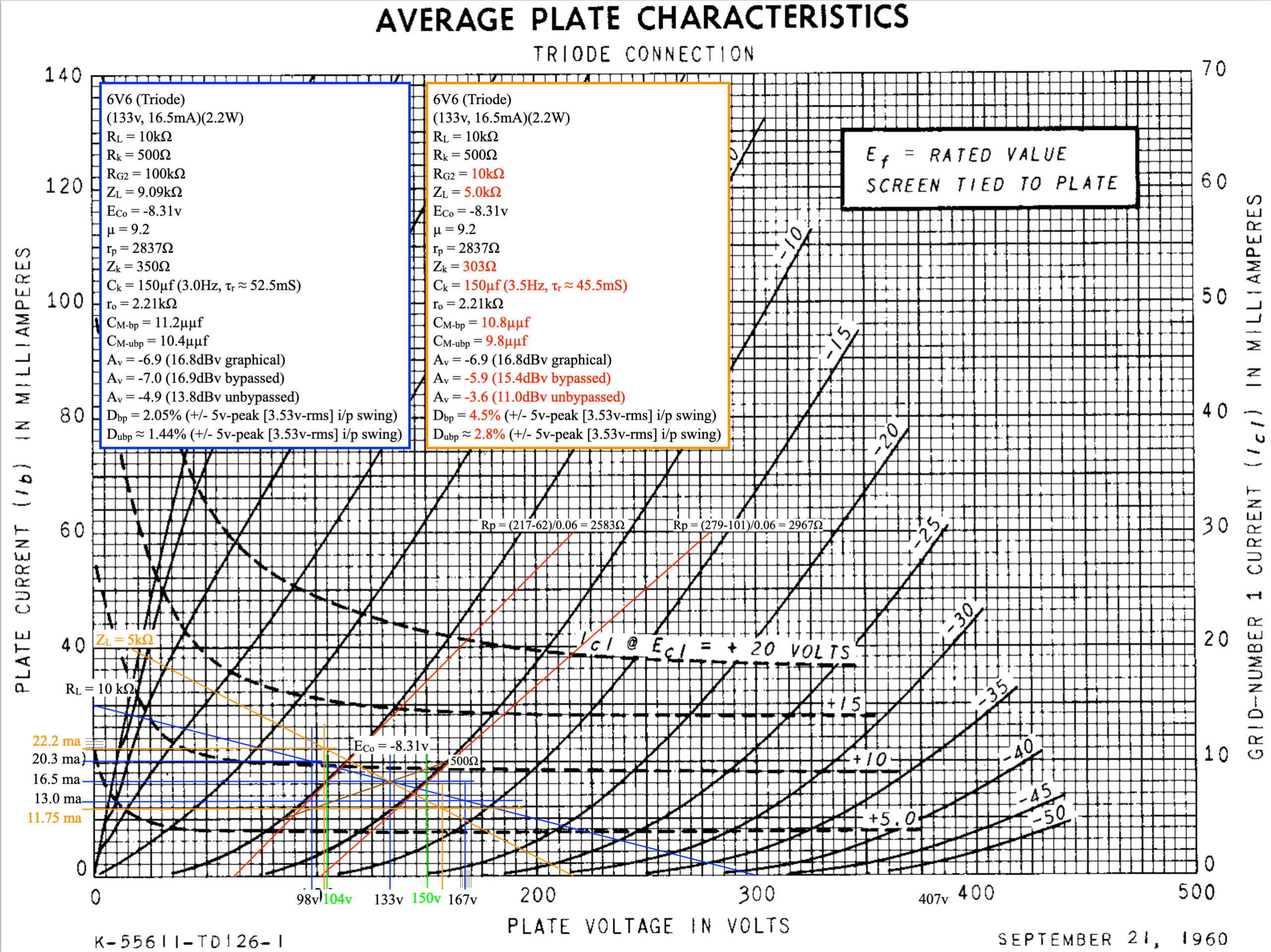
There is a lot going on in the load line design. This is a design with B+ set at 300v and a load resistor of 10kΩ. It uses a 500Ω cathode bias resistor and is biased at Vp=133v, Ip=16.5mA, Eco = -8.3v. The first set of data contained in the blue box is for the design with a 100kΩ output resistor.
The data listed shows the gain to be about 17dB with distortion at about 2% for a 3.5v-rms input. The stage output impedance is about 2.2kΩ. However as I said above, it’s driving low impedance loads where problems occur. The orange box contains the operational data for the same stage with an effective output resistance of 10kΩ. This is to simulate driving a typical solid state amplifier. Here things aren’t so well behaved.
With the low impedance load the distortion jumps to 4.5% for the same input. Not only this but the low frequency performance gets worse. The gain also drops to a little over 15dB with this load. Still, if looking at the stage in isolation I can understand how someone might want to try it. However, before going off and building a prototype, maybe we should look at the other design.
This design is for a small power triode, the 12B4. This is one of those television tubes designed primarily as a vertical deflection amplifier. Not only does it have a lower µ and plate resistance than the triode strapped 6V6, it is a very robust tube. Here is the load line design.
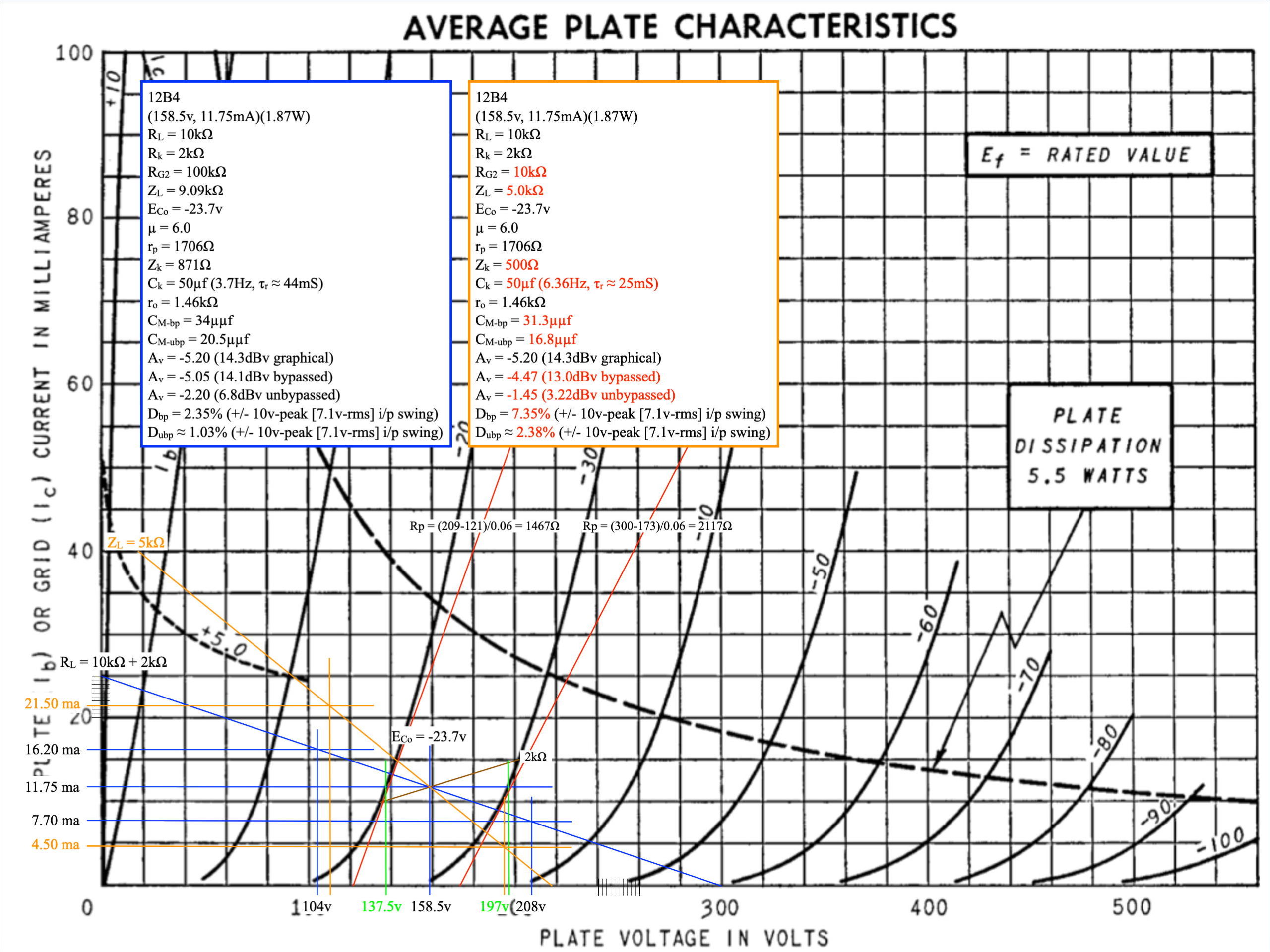
As before, this is a design with B+ set at 300v and it uses the same load resistor of 10kΩ. It uses a 2kΩ cathode bias resistor and is biased at Vp=158v, Ip=11.75mA, Eco = -23.7v. Also as before, the first set of data contained in the blue box is for the design with a 100kΩ output resistor.
So let’s explore how this triode stacks up against the 6V6. First off gain is about 14dB so about 3dB lower than with the 6V6. This may or may not be a concern as usually preamps have too much verses too little gain. This stage has much lower distortion being about 40% lower than the 6V6. The output impedance of this stage is also about 35% lower than the 6V6 stage, 1.46kΩ vs 2.21kΩ. So at first glance, this stage should be much better at driving low impedance loads.
Shifting to the case with the 10kΩ load resistor some things become apparent. Distortion increases as before going to 7.3% with a 7.1v-rms input, however this is still lower than the 6V6 stage. It is important to remember that the figures for the 6V6 stage were quoted at a 5v peak swing on the input. The numbers on the 12B4 stage are for a 10v peak input swing. To directly compare the distortion numbers one must either double the 6v6 numbers or halve the 12B4 numbers.
The loss in gain is only about 1dB going from a high impedance to low impedance load. This means that the stage behaves much closer across differing loads than the 6V6 stage. As expected, the Miller capacitance of the triode is significantly greater than the 6V6 however even the triode levels are not a problem for audio frequencies.
The last thing I would like to address is how the stages compare in overdrive characteristics. The 6V6 stage will go into grid conduction at about 8.3v. This will be abrupt and generate lots of odd order distortion. The 12B4 stage will go cutoff before ever seeing grid conduction. Compression will be more gradual and will add even order distortion. It can also reasonable handle twice the input voltage swing than the 6V6 stage. This is a significantly more desirable overdrive characteristic than the grid conduction case. It could be argued that one could increase the 6V6 bias voltage to get lower on the load line but this invites added distortion on a fixed load line. The the stage distortion is already almost twice the 12B4 stage.
Conclusion
I am not suggesting that you can’t or shouldn’t build a low gain 6V6 stage. Instead I am suggesting that given a set of requirements, there are better ways to build the stage and better tubes with which it can be accomplished. My hope is that this simple example will illustrate this fact.
I usually attempt to stress making good design decisions before attempting to build something, and that’s all I’m doing here. It’s easy to just throw out some idea in a forum or email discussion. But it’s not that much more difficult to look at some alternatives and potentially arrive at a better performing and a well thought out design. I’m just suggesting taking that small additional step before moving forward.
As always, questions and comments are welcome.
Here is the one BIG FLAW in the analysis here regarding using a triode-connected 6V6 or 6AQ5 as a line output/driver stage:
Look at the terrible point on the load line being selected in the example: Under 150 volts plate-to-cathode and under 20mA.
That’s little more than setting the triode-connected 6V6 up for failure !
The most cursory glance at the plate curves indicates clearly a triode-connected 6V6 or 6AQ5 shows that a much different operating point is obviously required for low distortion and high output.
The solution: set the static operating point at around 250V plate-to-cathode voltage and right around 40mA.
A quality plate choke can be used (or a quality line output transformer) can be used.
This way the triode-connected 6V6 or 6AQ5 will be fantastic line output driver or SET amp drive stage.
BTW: The 6V6 or 6AQ5 tubes, when strapped as triodes and run at an appropriate operating point –guys these are absolutely FANTASTIC sounding as triode tubes.
You can also make a superb 1-Watt output headphone amplifier using the same operating point and utilizing a 5k to 8-Ohm output transformer. Keep a 600-ohm shunt across the output transformer secondary, but otherwise simply drive any headphone within in the 8-ohm to 300-Ohm impedance range directly from the 8-ohm transformer output. Absolutely no efforts at output impedance matching are necessary beyond not going lower than perhaps 6-Ohms load.
A 6DJ8, or 6SN7 of 6CG7 etc fed by a 47K audio-taper stereo pot can be used as the voltage driver stage for a 1-Watt stereo headphone amplifier utilizing the triode-connected 6V6 or 6AQ5.
Incidentally: if you use quality audio output transformers with the triode-connected 6V6 of 6AQ5, and build a properly robust power supply, then absolutely no apologies are needed as far as sheer sound quality, even as directly compared to DHT tubes such as the 2A3 or 45. The properly set-up T-C 6V6 or 6AQ5 is just that good.
Cheers,
–Thomas
Did you read the post? I didn’t say that you couldn’t use 6v6s as preamplifiers, I said that there are much better solutions than trying to repurpose a beam bower tube as a simple voltage amplifier. I also discussed edge case conditions which are very important to preamp operation.
As an aside, you have the triode mode operating mathematics exactly reversed. The 250v,40mA operating point has significantly higher distortion than the 133v,16.5mA operating point I used in my example. Unless, of course, your goal is high 2nd order harmonic distortion (which is sometimes the case). For a good discussion of distortion in triodes, see Reich, Herbert J., “Theory and Applications of Electron Tubes”, 1944, McGraw-Hill Book Company, Inc. sections 3-23 to 3-25. In general, raising the effective load impedance on a triode reduces the distortion. This is born out by the term signs in the series expansion of the plate current relation.
This is a little off topic, but what are your feelings toward pentode preamps? It is not too common, but I have seen schematics with a cutoff pentode like the 6SJ7 in front of a power pentode like a 6l6 for a SE amp.
As standalone audio preamplifiers most pentodes have far too much gain to be useful. They would require much feedback to control the gain and that kind of defeats the original purpose. I would never recommend a pentode in that role. As for using pentodes as drivers, I think you’ll notice in virtually all those designs there is feedback to control the gain.
In a feedback amplifier, the total gain is equal to the forward gain (Af) over the 1 plus the loop gain (Af*β). What Black showed subsequent to his 1934 paper was that if forward gain (Af) is made very large (for example by using pentodes), then the overall amplifier gain collapses to 1 over feedback factor (i.e. β). This means that the amplifier gain function (in the pass band) is independent of tube and circuit factors.
This realization was really a benefit to the design of RF small signal front ends. You’ll notice that virtually all the small pentodes were initially designed as RF small signal amplifiers. This eliminated much of the “fiddling” required to make radio receivers functional.
However, the builders of audio amplifiers pounced on this like wolves on a wounded sheep. This meant they could compromise design (i.e. make amplifiers a lot cheaper) and let the feedback fix the variability issues. There are some other design factors of which to be aware, however this change ushered in a new era of feedback audio amplifier design for the masses. And it prompted tube manufacturers to produce what they call “audio signal pentodes” which were in reality just warmed over RF pentode designs.
My general two personal rules are “no feedback in audio amplifiers” and “signal pentodes are for RF circuits”.
Thanks for sharing the insights. I enjoyed reading your answers, especially the “personal rules” at the end. It seems a number of these radio tubes are floating around, and it makes one wonder if they could be repurposed for other uses. However, there are just more prudent options for a preamp.
Mullard engineers tended to favor sharp cutoff pentodes as audio voltage amplifiers with global NFB to keep things under control. On the RF and IF side, remote cutoff pentodes were used. The gain of a remote cutoff pentode can be controlled with grid bias voltage – very handy for implementing AVC and AGC in receivers.
Just curious, back in December you wrote about the potential of a KT88 as a strapped triode. Have you thought about this idea more since then?
I have a modified KT-88 triode-strapped design that I’ve been looking at. It produces peak power somewhere between 4.5W and 7.5W per channel depending on the B+ voltage. I need to play with power supply designs because the bias point will drive output transformer choice. Higher bias current will drive a larger output transformer. However, I think this project is still a little ways off. My real focus right now is trying to get the 6AS7 SET chassis done so that I can get that amp up and running.
Why would someone want to use a 6V6 as a preamp or voltage amplifier tube? All of the tube manuals I have access to state that the 6V6 is intended to be used as an audio output tube. It would seem to me that it would be optimized for its intended purpose, likely to the detriment of other uses.
I really think it has to do with people looking for low µ tubes for preamps. I think some people also tend to latch on to the statement in some data sheets about the 6V6 being suitable for use as a triode connected vertical deflection amplifier. Because they don’t really understand CRT deflection circuitry, they think that means triode strapped voltage amplifier.
Like I said, I’ve been hearing about this on and off for at least ten years. There are a lot of misconceptions about preamps and other gains stages and I think some people get fixated on certain characteristics. Once this happens they can’t let go and seek balanced solutions. At least this is my perception of the situation.
Wouldn’t a 6SN7 be a better option for these people? Octal, low μ , two triodes for stereo. As you said, they see triode connected vertical amp in the 6V6 data, but they don’t realize that the vertical output is actually a power amplifier, not a small signal amp.
For low gain preamps I would recommend, as you say, the 6SN7 and also the 12AU7, 12BH7, and 12B4. I especially like the 12AU7 because, when teamed with a standard volume control, it gives almost a perfect -20dB to +20db gain variation. Something that I consider ideal in a preamp handling different sources at different levels.
I’d add the 6CG7/6FQ7 to that list. Super little dual triode perfectly suited for Preamp stages. In fact, this tube may reside in the 4S preamp I’m wrapping up. Very minor change to heater connections and make sure transformer will give 0.6A. I recommend giving those tubes a whirl, you will like them.
I really like the 6CG7/6FQ7. Like their bigger cousin the 6SN7 they are low noise and just about right for preamps and drivers. The Lacewood uses a 6SN7 driver and the 6AS5 Micro-power UL uses a 6CG7 driver. Both sound excellent.
I’m compelled to add to my last comment. It looks like I’m suggesting a drop-in replacement of 6CG7 in the 4S Preamp. I am not. The 6CG7 has different operating point and current requirements (as well as different heater spec as mentioned). I want to make sure nobody gets the wrong idea. I still consider the 6CG7/6FQ7 a very musical preamp tube. Using a 22K (2W) plate R, 1.5K (0.5W) cathode R, and 300V B+ in the otherwise 4S Preamp topology. Current is more than 12A*7 tubes (data sheeet says 9mA per plate; sounds right). Hopefully folks can give these tubes a try. You can thank me later.