
Back in November, in my post concerning Tubes and Tube Testers, I talked about how I was not really a fan of generic tube testers. In that post I sited a statement from the RCA “Receiving Tube Manual”, RC-30, about testing tubes.
The tube tester cannot be looked upon as a final authority in determining whether or not a tube is satisfactory. An actual operating test in the application will give the best possible indication of a tube’s worth.
So I thought that as a simple demonstration I would collect some data from a couple of tubes; one new and one rather ‘used’. The results are really kind of surprising.
Here are the two tubes I chose to test; both ECC82/12AU7s.
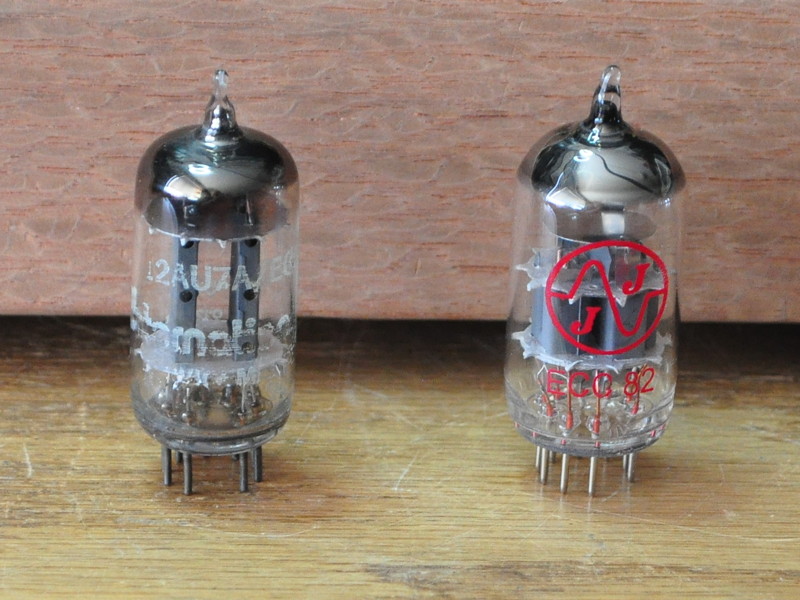
On the left is an older “International” branded 12AU7A/ECC82 and on the right a brand new JJ ECC82. The JJ is a tube I use for new circuit testing and has very few hours on it. The other is just a miscellaneous tube that was pulled from an old piece of equipment. On my TV-11 emission type tube tester, the JJ registers as “Good” and the International registers on the line between “weak” and “good”. But in reality, there is not much difference based on needle position. So I decided to gather some data under various load conditions.
DC Bias Testing
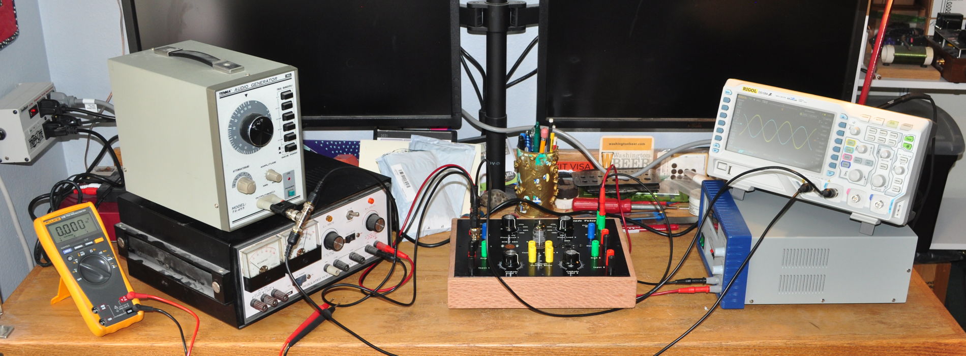
I decided to use my test jig and gather load-line data at set of different grid bias points. Heres the initial test setup.
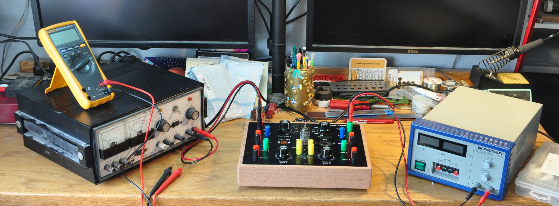
I used a B+ voltage of 300v for all test conditions. My procedure was to first set the plate load at one of two values; 47kΩ and 100kΩ. Once the load was selected, I would measure the plate voltage and grid current at several different grid bias voltage levels; 0v, -2v, -4v, -6v, and -8v, for both triodes. Once I started collecting data I realized that I could not always get a full -8v grid bias with the 5kΩ bias potentiometer in my test jig. So my comparisons are only for the other four bias voltages. Once I gathered the data I plotted the bias points on a standard set of 12AU7 plate characteristics. Here is the initial plot.
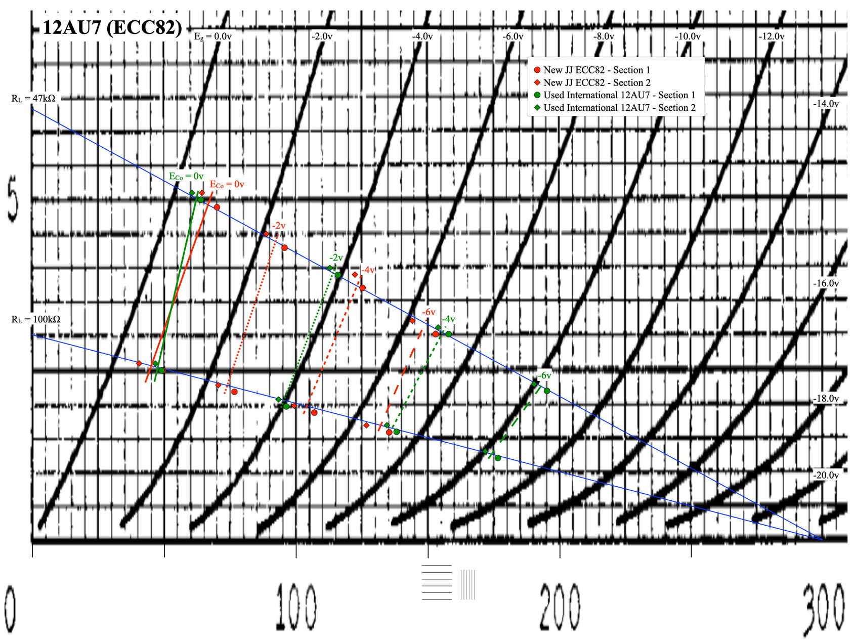
In this plot I’ve shown the (Vp,Ik) voltage current pairs for every test point. The points in red are for the JJ tube and the points in green are for the International tube. Round points are section 1 of the dual triode; diamond points are for section 2. I have also drawn in lines between the two load lines showing the approximate location of the bias curves for each tube, at each bias voltage.
The data for the JJ seem very consistent with the published characteristics. Plate voltages are slightly higher than the characteristics curves but the difference is very regular for all four bias points. The data for the international tube is a different matter. Although a virtual match at zero bias voltage, as the bias voltage increases (in the negative direction) the currents are falling much faster than expected. In essence, the current flow is much more sensitive to bias voltage.
This condition is actually indicative of low cathode emission. If you think of the flow of electrons coming off the grid as a stream, it actually takes less grid restriction to impede the flow of the stream as it decreases in overall size. This moves the points farther down the load line and increases the plate voltage. This also highlights the fatal flaw of an emission type tube tester. These testers typically test at zero grid bias and as shown above, the zero grid bias lines are very similar. But the curves are much different as bias voltage increases.
During testing I also noticed something I considered odd. The JJ tube at 12.6 volts drew a full 150mA of heater current. However, the International tube, at 12.6 volts, only drew 120mA. At first I suspected that this might be a clue to the emission falloff. Could it be that the cathode was not really up to temperature? So as a test, I retook all the international data after increasing the filament voltage enough to get a full 150mA of heater current (15.4v in this case). The data is informative but not the smoking gun I assumed it would be.
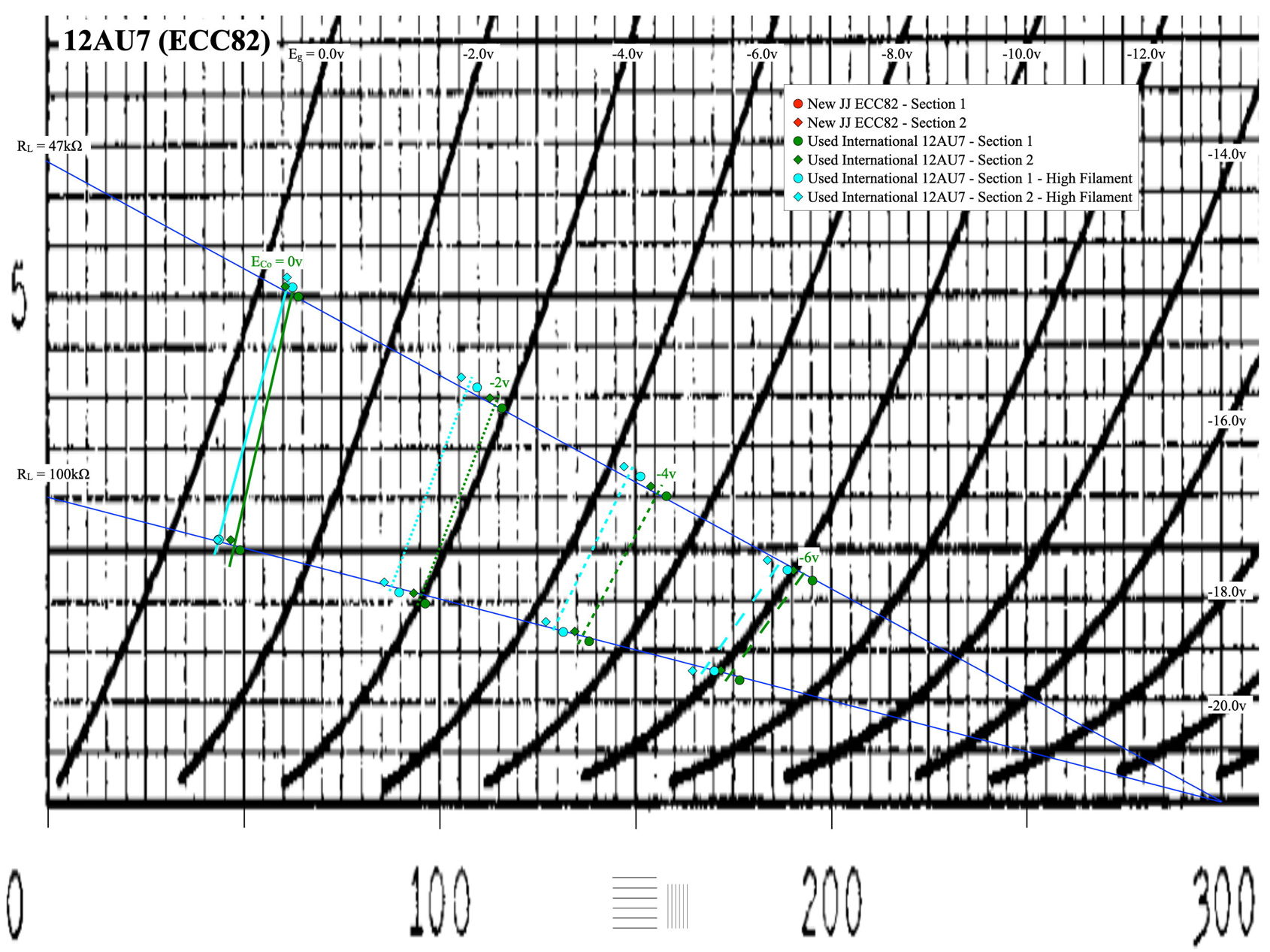
On this plot I’ve shown the data for the international tube at the two different filament currents. The light blue being the data from the hotter cathode. As expected, the increased heater current did result in increased emission, but the increase is very uniform over the various grid bias voltages. Unfortunately, I cannot blame the heater for this tube’s performance. The evidence seems to suggest that the cathodes in this tube are losing their emission efficiency.
For completeness, here is the data I collected during the DC bias testing in tabular form.
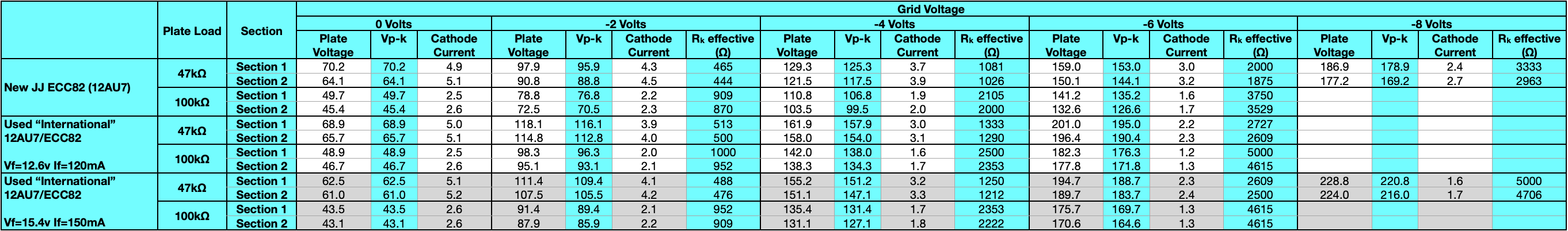
This data includes all the data taken including the -8v bias data not included on the plots.
AC Performance Testing
Normally we could stop at this point, call the international tube “bad” or “end of life”, and move on. But the statement from the RCA manual said “An actual operating test in the application…” and the DC testing, while extensive, is not an operational test.
So I decided to go ahead and AC test both tubes. As the DC bias data points for the sections were very close in each tube, I preformed the AC testing on only section 1 of each dual triode. Here is the expanded test setup.
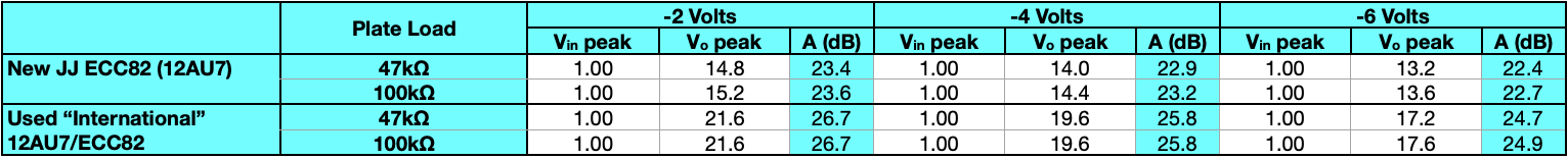
In this set of testing the triodes are in a common cathode configuration with resistive plate load (47kΩ or 100kΩ) and are cathode biased. I used a 1V peak input signal for all conditions and measured the peak output voltage with the oscilloscope. All data for AC testing was with a filament voltage of 12.6V.
This data is much more interesting than the DC data. First I’ll present the plot of the amplifier stage gains.
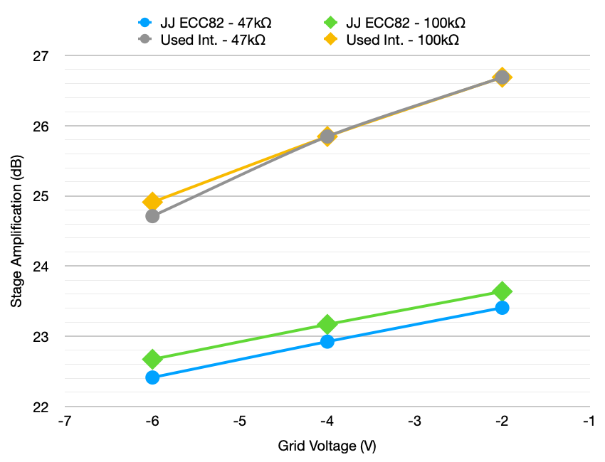
I was actually shocked at this difference. The older tube with the suppressed cathode emission actually exhibited approximately 3dB GREATER stage amplification than the new tube. However, stopping to think about the bias plots above, I concluded that as the emission went down the current flow became more sensitive to grid voltage. This means that, in essence, the gm of the triode must have increased. And because the plate characteristics have not changed, if gm increases then µ must also increase. Here is the tabular amplification data.
Discussion of Findings
Having discovered a positive aspect of this “lower emission” tube, there have to be some negative aspects as well. And these have more to do with how the tube behaves in an actual circuit designed for a 12AU7.
In the DC bias testing data table, there are columns labeled “Rk effective”. These resistances are calculated from the measured cathode voltage and cathode current using Ohm’s law. The way my test jig is designed, it does not have a direct readout of the cathode resistance dialed into a circuit. During the test jig design process I decided that I was more interested in exactly what conditions the tube is tested under, and less on what circuit constants got it there. And since I can measure both the actual cathode voltage and current, the cathode bias resistance is easily calculated.
Using this information it is more straight forward to see what would happen if the old tube goes into a circuit. I am going to focus on the -4V grid bias part of the table, looking at section 1 of the two tubes, with 47kΩ plate loads. From the table, the JJ required approximately 1080Ω to get to the bias point. But the International required 1330Ω to reach the same bias. This is because the cathode current is lower for the International tube; 3.0mA verses 3.7mA.
From this we can conclude that given a stage designed with a 47kΩ plate load and a 1kΩ cathode bias resistor, the JJ would be biased at about -4V (perhaps slightly less). However if using the international tube, the bias would be significantly less. And as the cathode emission continued to erode, the bias voltage would continue to decrease. If this stage was a small signal amplifier with an input signal in the range of millivolts this wouldn’t matter much. But in a stage designed for at least 3v peak signal voltage like an audio line level input, this reduced bias could result in the stage going into grid conduction and introducing excessive distortion.
This is another clue as to why those “tested weak” tubes sometimes work without issue in a circuit and sometimes they don’t. It has more to do with the nature of the circuit, than the exact characteristics of the tube itself. And the reason real that the line in the RCA manual is so true. Until you put the tube into the circuit it is to be used in, it’s difficult to really determine if the tube is suitable or not.
The Final Test
Sometimes, after working out an issue like this one, I begin to wonder if I really have arrived at a real conclusion, or if I’ve just convinced myself that I have with a lot of measurements and numbers. So to assuage that particular doubt I have conducted one last test. I am currently playing some light jazz through the “Color” preamp in front of a class-d amplifier. In the gain stage slot is the International 12AU7/ECC82 tube. And it sounds really good.
Regardless of what all the measurements say, this is the real test. I could have thrown that tube on the trash heap as “worn out” but I’m glad I didn’t. Apparently it still has a lot to give, so long as I remain observant enough to realize it.
As always, comments and questions are welcome.
An interesting series of articles Matt showing the worth of the test jig and also trusting your ears. I wonder if anyone has worked as hard as you to further hifi tube amp understanding in modern times. The second hand German 12au7s I bought on eBay I was a bit worried about not really knowing how much life was still in them although advertised as testing good. They seem to sound fine in the 6AS7 amp but I plan to buy some new JJs to have on hand in case.
Regardless of what’s in the equipment, it’s always good to have spares. I think I currently have about 10 12AU7s in my stash. I like to remind people that the reason vacuum tubes plug into sockets is because they fail and need to be replaced periodically. If only modern electronics was so forgiving. 🙂