
I took some time this week to get several coats of oil on the chassis for the Dual Triode Test Station. Even though I’ve already used it for the mystery tube investigation and to compare some 12AU7s, it’s good to have it finally complete.
Here’s how it looks now that it’s complete with it’s lacewood chassis.
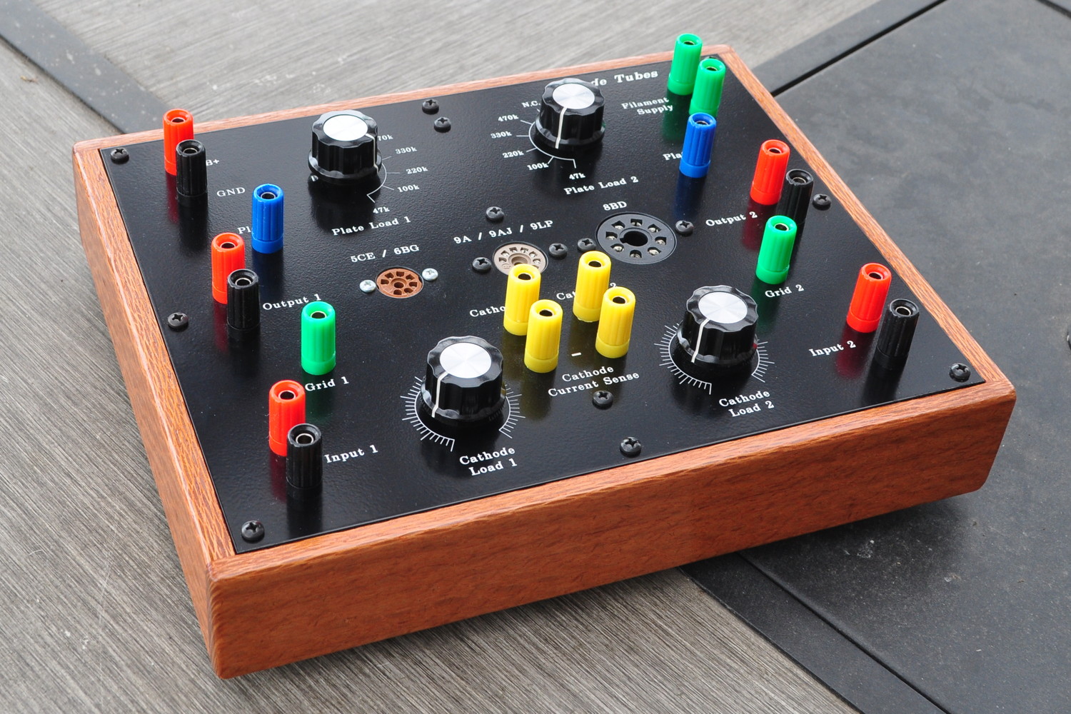
I am very happy with how it turned out and how useful it has been already. I have a feeling that this test jig is going to get a lot of use. And here is a direct look at the face plate with everything installed.
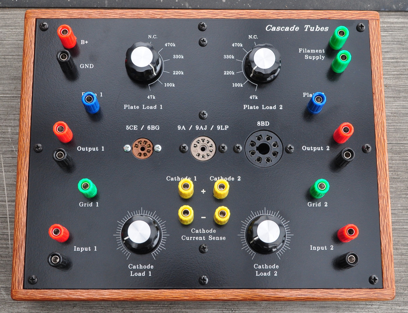
Again, I am very happy with the face plate provided by Front Panel Express. It really gives this piece of equipment a very finished and polished appearance. Soon I’ll get a separate project page put up with all the information on this little unit and how to use it for best results.
Now I guess I have no excuse for not getting back to serious work on the 6AS7 SET.
Looks just beautiful Matt! When FPE makes a panel like this, is there an option to mask off the powder coating around a mounting hole (e.g. to make a ground connection to a terminal strip) ?
There may be (I didn’t ask) but my guess is that it would be expensive because the powder coating is done between the drilling and the engraving.
A simpler method is to simply have one hole drilled undersize and then when you get the plate, tap the hole to take a screw (e.g. like a 6-32 thread). Then thread the screw in from the front and on the back side you now have a grounded stud. Or you can just hit the area around a hole on the back with a little sandpaper.
Pingback: 6L6 SE-UL Primed for Progress | Cascade Tubes
A very lovely bit of equipment. Much nicer than the slab of wood…… although I can appreciate that look too. It’s my wife who wants everything to look “presentable”. With your kit, I would maybe be allowed to work in the house! As opposed to exile in the shop.
One question, how is Cathode Load scaled?
The cathode load is set to obtain a specific cathode voltage. This voltage is measured between the cathode pin and any ground (black) terminal. A typical quick check of a triode might go as follows:
1) Pick a B+ voltage and a plate load resistance value.
2) Draw a load line to determine the load line intercept points with the constant grid voltage contours.
3) Choose the intercept point closest to the desired operational value.
4) While measuring the cathode voltage, adjust the cathode load to obtain the desired grid bias.
5) Measure and record cathode current (Ibo) and plate-to-cathode voltage (Ebo).
6) Compare measured values with load line values to determine how close the tube is to the “family” performance.
This is essentially an emission test but in a much more representative configuration than used by most tube testers.