
With all the distractions this week, I’m not quite as far along as I would have hoped. But all the top plate wiring is done, the power supply sections are complete, and the 6AS7 power stage is complete.
Here’s how the top plate looks from the bottom. It’s finally starting to look like an amplifier.
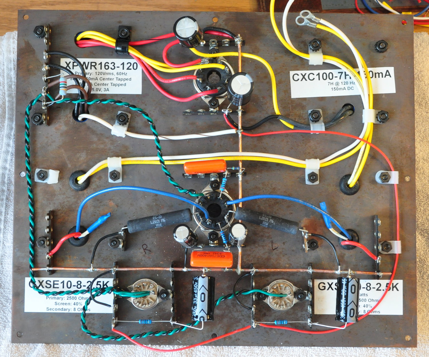
At the top of this picture you can see the 33µf primary filter capacitor and the 100µf cap that comes after the 7H primary filter choke. At the bottom you can see the 1kΩ/33µf power supply filters for the left and right drivers.
In the center of the picture is the wiring for the power stage. I used oversized power resistors, 10W rated dissipation verses the 5.3W actual dissipation because they had a much larger surface area to spread out the heat. The coupling capacitors are CDE 716 Series 0.1µf capacitors. This value puts the -3dB low frequency for this coupling at about 2.8Hz for a 20Hz loss of only about 0.6dB. With the natural low end response of the drivers and the reasonable transformer performance, this amp should have a nice well controlled low frequency response.
Next comes wiring the driver sections. Once that’s done I’ll install the top plate on the chassis and make all the appropriate connections. Then it will be time for testing.
As always, questions and comments are more than welcome.
Thanks for the explanation Matt. Yes, I can understand you trying to stay away from small chassis’s, all those chokes, transformers and valve base’s take up more space than you think when you start. I’ve spent hours myself playing tube type twister to fit components and reach them with my soldering iron!
I have a 12″ by 10″ chassis in mind for this 6AS7 amp.
I’m enjoying how you’re progressing.
It looks very tidy Matt and I like the transformer/choke labels on the underside of the top plate.
Just a question about the layout, in your earlier projects like the 6CY7 and the 6336 you separated the power supply from the audio part of the amp with an aluminium plate to minimise hum. In your recent designs you haven’t. Is this due to the larger chassis making it unnecessary, or some other reason?
I started to use an internal shield after my disastrous results with the First Amp. I was concerned about high voltage interaction under the top plate. However, what I’ve learned in the 10 years since is that with larger chassis, proper component layout, good grounding, and careful lead dressing, it is not really required. It is sometimes nice to provide some more internal mounting space for chokes or capacitors.
I would only go back to an internal shield arrangement if I was working in a very small space. And I’ve made every attempt to swear off small chassis going forward.