
I just got a notification from Edcor. The power transformer I ordered for the 6L6/KT88 SE-UL Amplifier on the 2nd of May (just 9 days ago) shipped today! I thought I was going to have a lot more time to get the spalted alder chassis into shape.
For whatever reason, Edcor is shipping product in record time lately. The last Edcor order I placed for the output transformers and a power choke, back on March 29th, shipped in less than two weeks and showed up on April 12th. This is definitely the time to place an Edcor order if you’re ready to build. I feel like I should send Brain Weston a thank-you card.
So now that I know my transformer is going to be arriving in a few days, I’ll be able to check the final mounting dimensions on my layout drawing. I always check these when the iron arrives just so I don’t end up drilling in the wrong locations. Here is the current top plate layout.
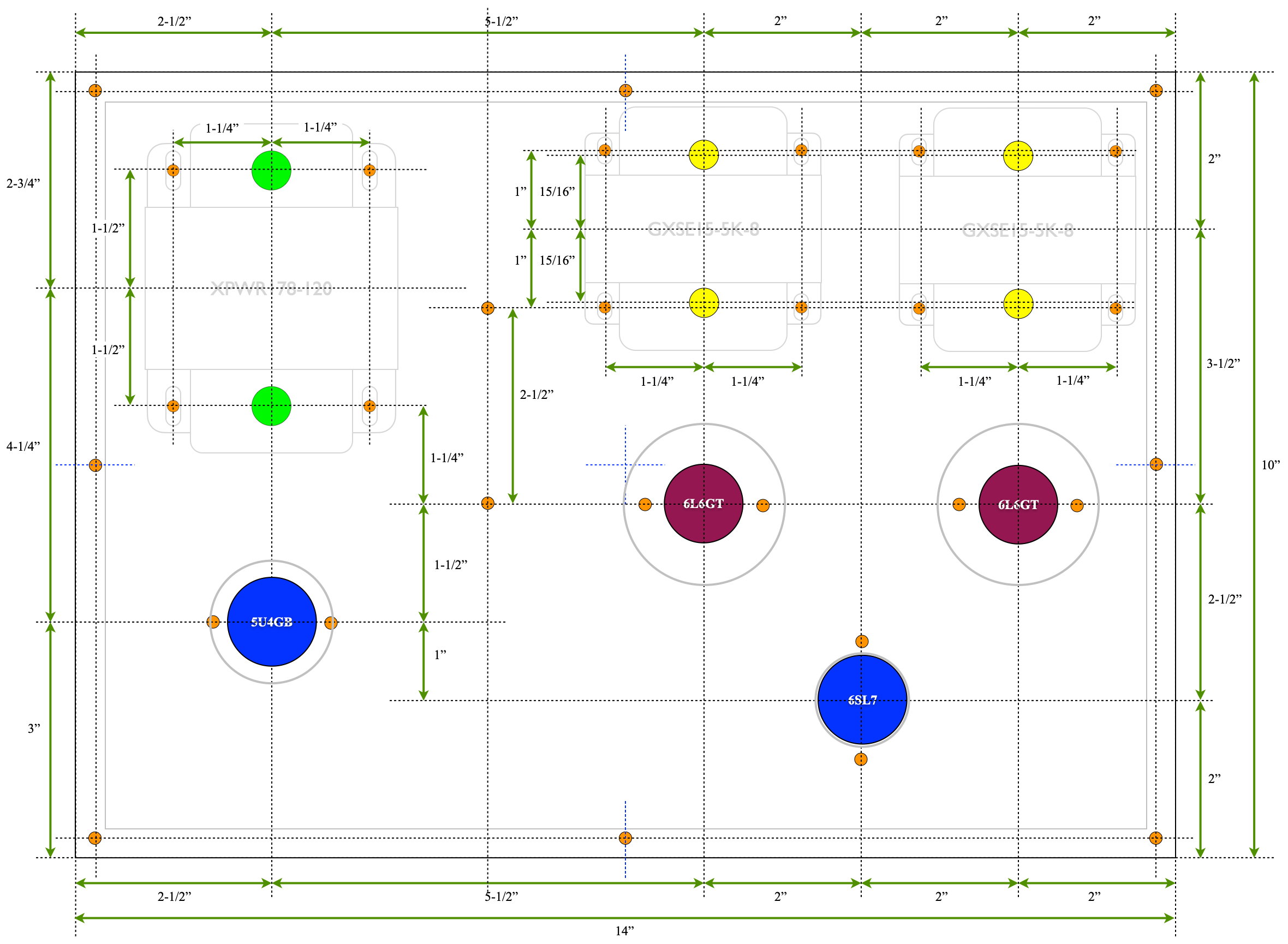
It’s a nice clean layout. The only disturbance is what will be two small screw heads between the power transformer and the left output transformer. These were necessary to accommodate the internal mounting of the physically large filter capacitors. Here is the internal layout showing all the plate wiring.
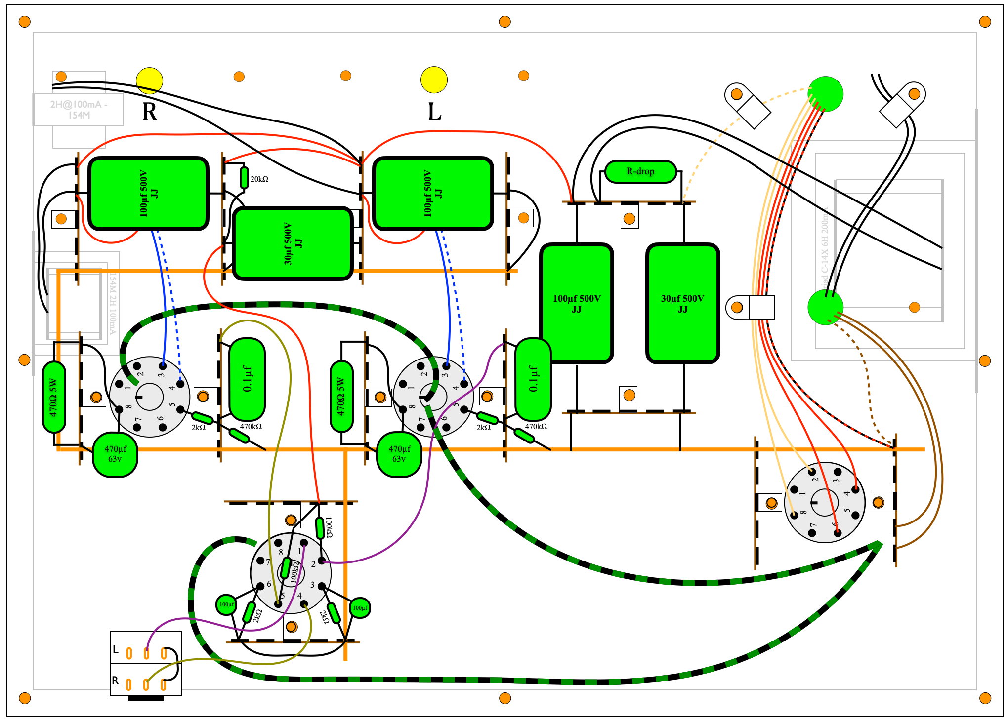
With this work complete, I don’t anticipate any major layout issues.
Now I need to get into the shop and start working with that spalted alder. I also need to finalize the chassis depth. Right now I’m assuming 3″ (≈76mm) because that would make the front profile the same size as the Lacewood chassis; which I like. However, I need to look at the spalting pattern. If there is some really nice figure I’d like to include, I may make the chassis a little deeper.
As always, questions and commends are welcome.
I’ve settled on 3.25-in for wood plinth type chassis. The extra 0.25 in is more handy than you would think. Plus there’s more beautiful wood to show off. The last two projects were quarter sawn European Beech — fancy in an understated way. The spalted alder will look stunning at almost any depth.
I just realized I must be a relic, I still do all layouts on paper with pencil. Haven’t felt the need to go digital. Paper layouts in my heavily worn notebook seem to work. But out of curiosity, what are you using to draw layout?
I’m rather excited about this 6L6 amp. I start one of my own later this year, but will have to be PP to take advantage of gifted very high-end output transformers. So….no interest at all in PP topology?
I started out with paper for amp layout, but graduated to the computer when I started to buy erasers in bulk. 🙂 I currently use Apple’s Pages program. But I can build them in PowerPoint almost as fast. I’ve tried some of the more advanced CAD packages and, whereas they are far more powerful, I always seems to find myself trying to do something simple and the package won’t let me do it.
Years ago I happened into two NOS sleeves of five each (so ten total) of JAN 6005 beam power tubes. These are the industrial version of the 6AQ5 (little brother to the 6V6). Those ten tubes sometimes call to me to build a little PP-UL amplifier. But to really do it justice I would have to do some experimenting to optimize the bias points. It just never seems to get very high on the priority list.
Matt,
Have you ever written up any specifics for using Pages to do these layouts? They look great. I’d like to follow your lead.
Oops. First off I misspoke in my comment above, I use Apple’s “Keynote” and not “Pages”. Keynote is Apples presentation program akin to Microsoft’s “PowerPoint”.
As for using either Keynote or Powerpoint for layouts, it’s a fairly straightforward process. The layouts are all just various combinations of stock shapes and text. The real issue is getting comfortable enough with the software to quickly pull up the tools you need. When I first started using Keynote I was painfully slow. I took literally hours to lay out a simple top plate with several holes. But as I’ve gotten more familiar with the usage of rulers, tool panels, and hot keys, I’ve become substantially faster.
I also do a lot of reuse. I have documents with tube socket pinouts, terminal strips, inductors, transformers, potentiometers, cable clamps, even dimensional arrows. I also have a stock set of pre-dimensioned and color coded holes. All of these have been developed one at a time. Whenever I finish one, I like to add it to a “library” document from which I can copy and paste in the future.
The real reason I like to do the layouts in software is not really even speed. I could do it much faster by hand (at least initially). The real benefit is the ability to move things around and make adjustments until it looks about right. It’s the edit-ability that is the real power.
Sorry I don’t have a more detailed set of approaches or instructions. But if you just jump in and start doing some layouts for simple things, I think you’ll be surprised how quickly both your speed and accuracy improve.
Thanks for all the great info. I’m a Mac guy, so Keynote is just a click away. Sounds like your process is not dissimilar to what I do for PCB layout. Over the years I’ve invested a lot of time creating a library of part schematic symbols and PCB footprints. It sounds like you’ve done the same for your amp work in Keynote. I guess the question for me will be, how much up-front work will I need to do before I can do a layout more easily in software than manually. I’ll look into it. Thanks again.
Doesn’t really hurt you. At least the transformer will be on hand when you need it.
Never meant to imply it was a bad thing, just unexpected.