
I’ve been on vacation for the last couple of weeks but I’m back now and ready to get moving on the 6L6 SE-UL amplifier.
When I left I had marked up all the metal but had not started the metal forming steps. I believe things looked like this.
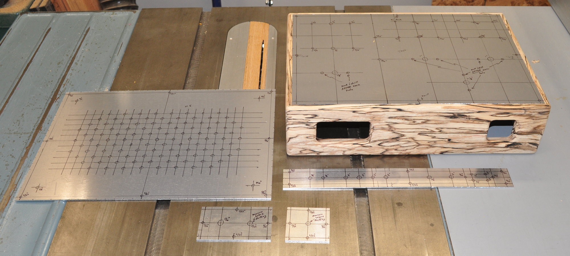
So I’ll start with the mounting holes and transfer these to the chassis. Then I’ll be able to start the chassis finishing work at the same time as I’m doing the metal work.
I’ve got a whole bunch of other tasks on my schedule as well, so I’m not sure how fast the amp work will proceed. But rest assured that it will be progressing in the next week or two.
As always, questions and comments are welcome.
So glad to see this! I’ve been playing with a similar amp built around the Hammond 290CX. Noval socket, for the driver, so I’ve been trying tubes like 12AU7, 6DJ8, 6N1P and 6N6P. Here’s my current schematic:
https://imgur.com/gallery/upqptge
I like the sound, but I know it’s not getting enough drive V for those big power tubes. Don’t want to drill the chassis, so think I may copy your circuit with a 6N2P as driver. Is there another 9 pin tube you’d recommend?
What’s the value of the coupling cap?
I know you don’t like NFB on the UL circuits, but I built this amp with switchable NFB and definitely like it with feedback.
And my build of the Lancewood v2 is my favorite amp, I listen to it every day. Thanks for putting all this great info out here for the rest of us!
As to my feelings on feedback, I suggest you review this blog post from 2017: A Note on Feedback
As for an alternative to 6N2P in the circuit you posted; do you mean 6N23P? It’s a 6DJ8 equivalent. I am not familiar with a 6N2P (6Н2П) designation.
The 6DJ8 has a µ≈70. So you should have sufficient forward gain in the feedback equation. The lack of drive voltage is likely due to the feedback level. The goal of negative feedback is to maximize the forward gain (A) and use a small feedback factor (β) so that the feedback gain equation simplifies to ≈1/β. I am guessing that you are applying too much feedback in relation to your forward gain. I would reduce feedback (perhaps using the 4Ω op transformer tap) before trying for additional forward gain.
Thanks for the reply. I do like the 6DJ8 / 6N23P driver, and the 6N1P is good, too. Fun to play with the cheap Soviet tubes. I’ll try your ideas on FB.
Thanks for the explanation. It helps me see how these values are the last line of the chart just before the conclusion in the 6L6 Optimization study.
Hope you had a good vacation.
Very good. We actually went through Yellowstone just a few days before the torrential rains that washed out roads and shut down the park. We had nice weather however.
Glad you’re back, Matt. I was wondering, and perhaps I missed it, where is the schematic for this amplifier?
I thought that I had posted the schematic for the 6L6 SE-UL before this, but apparently I was wrong. I went through the media library and the schematic is conspicuous by it’s absence. So here is the schematic for the 6L6 SE-UL out of my design notebook.
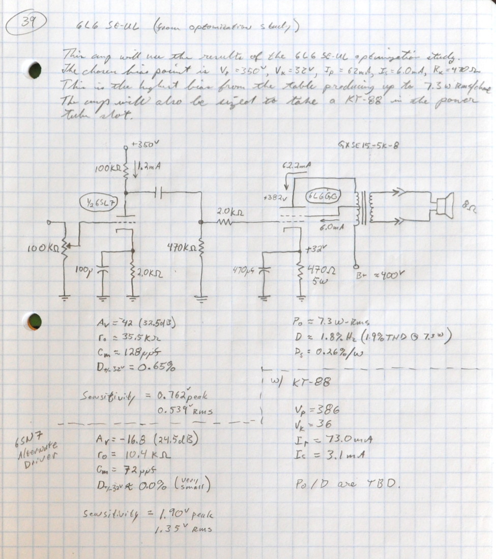
Sorry about this. I usually post schematics before I start a project.
Have you worked out the PS yet? If YES, do you have that schematic too?
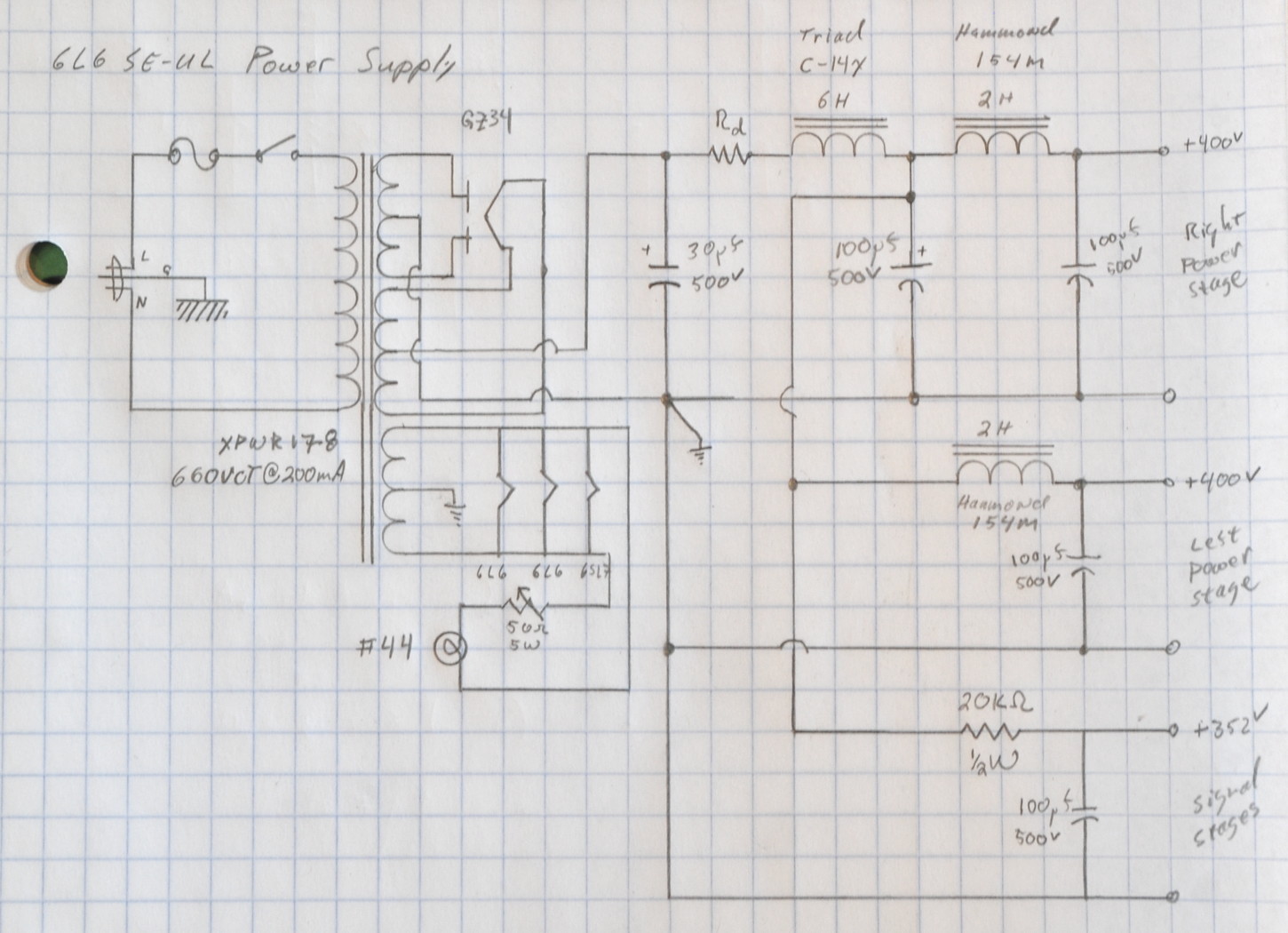
Yes. Here is that schematic as well.
I know previously you had mentioned only being able to test to 350v for 6L6. Can you remind me how you are doing the prototyping now for the 400v supply you have designed?
That’s not quite the case.
The point I made while discussing my test setup in the 6L6 Optimization study writeup was that my power supply only went to 400V so I limited the plate voltage to 350v so that I could still use cathode bias. Remember that in a cathode bias stage the B+ voltage equals the plate voltage, plus the cathode resistor drop, plus the load transformer drop.
The targeted 6L6 bias point I am using is the one with a B+ of 396v, a plate voltage of 350v, a cathode voltage of 32v, and a transformer drop of ≈14v (350v+32v+14V=396v). There is significant margin in plate and screen dissipation at this bias point. The additional 4v of B+ to get 400v will make virtually no difference as it’s only a 1% change.