
This topic is just the gift that keeps on giving. I first introduced the 4S preamp with the volume control on the output almost 12 years ago. And yet there still seems to be a tremendous number of misconceptions about the concept and performance ramifications of volume controls on the output instead of the input. This time the misunderstandings surround an output buffer cathode follower.
The specific issue which has arisen is actually about low frequency response when the volume control follows a cathode follower. This is the topology used in the 12AU7 “Color” Preamp project. For some reason, there is a serious concern about the volume control “interacting” with the output capacitor to radically change the low frequency response of the circuit.
Let me first state categorically:
There is no wrong place to put a volume control in the signal chain!
This statement alone will probably bring down legions of internet flames upon my head. But I stand by the statement. It is very important to keep in mind, each topology decision (i.e. where to place what) will have its own ramifications. However, if one understands what those ramifications are, then designing a well behaved and excellent sounding piece of equipment is still possible. What’s more, by rearranging the topology it may be possible to meet design requirements which may be impossible to meet in any one given arrangement. Topology is just one more degree of freedom in the design process.
As I have already discussed the output impedance and high frequency response in the first installment of this discussion, I am going to focus on the low frequency response and changes with volume potentiometer setting.
I wish to clearly state first off that, yes, there is a subtle effect on low end frequency response with volume control setting. However it is small and very manageable. What’s more, it is an effect which diminishes with increasing impedance of the load. So worst case is when driving the lowest assumed amplifier input impedance. And even in this worst case condition, it is entirely manageable.
I am going to start with the following schematic for analysis:
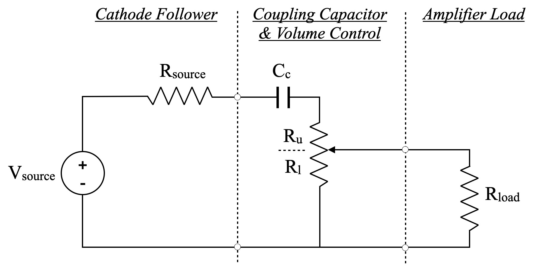
I have reduced the buffer stage to its Thevenin equivalent. In the case of the 12AU7 color preamp, the buffer output resistance is 491Ω. This is the value of Rsource. Cc is simply the coupling capacitor, and Rload is the input impedance of the amplifier to which the preamp is connected. I have broken the volume potentiometer into two pieces. Ru is the portion of the control resistance between the buffer output and the wiper contact; Rl is the portion between the wiper contact and signal ground. Note that Ru+Rl will always be constant. As one increases the other must decrease.
Using this circuit, it is a simple matter to calculate the -3dB frequency rolloff point for the circuit. The equations for this are as follows:
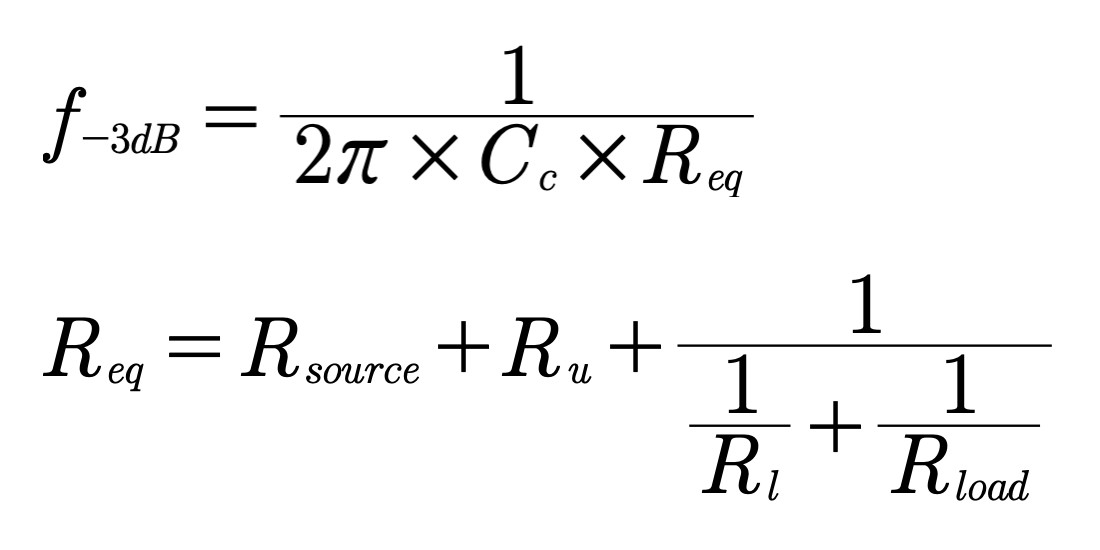
The basic formula is just the typical calculation for single pole frequency rolloff. The interesting part is the formulation of the equivalent resistance, Req. When calculating the frequency response it is important to account for all the impedances in the circuit. Note that the relation for Req does this.
First, it should be apparent from the schematic that the value of Rload will have a varying impact on the equivalent resistance as the volume setting changes. Rload is in parallel with Rl. When the volume control is at a low setting, Rl is small and the parallel combination with Rload has little impact, and the comparatively larger Ru value dominates. However, as Rl increases, Ru decreases and the load has ever greater impact. This case meets the limit at 100% volume setting where the load resistance is in parallel with the entire volume control and Ru is 0Ω.
It is not necessarily a simple matter to visualize how the resultant relation changes with control setting. The nonlinear nature of an audio potentiometer in combination with the changing values of Ru and Rl tend to complicate things a little.
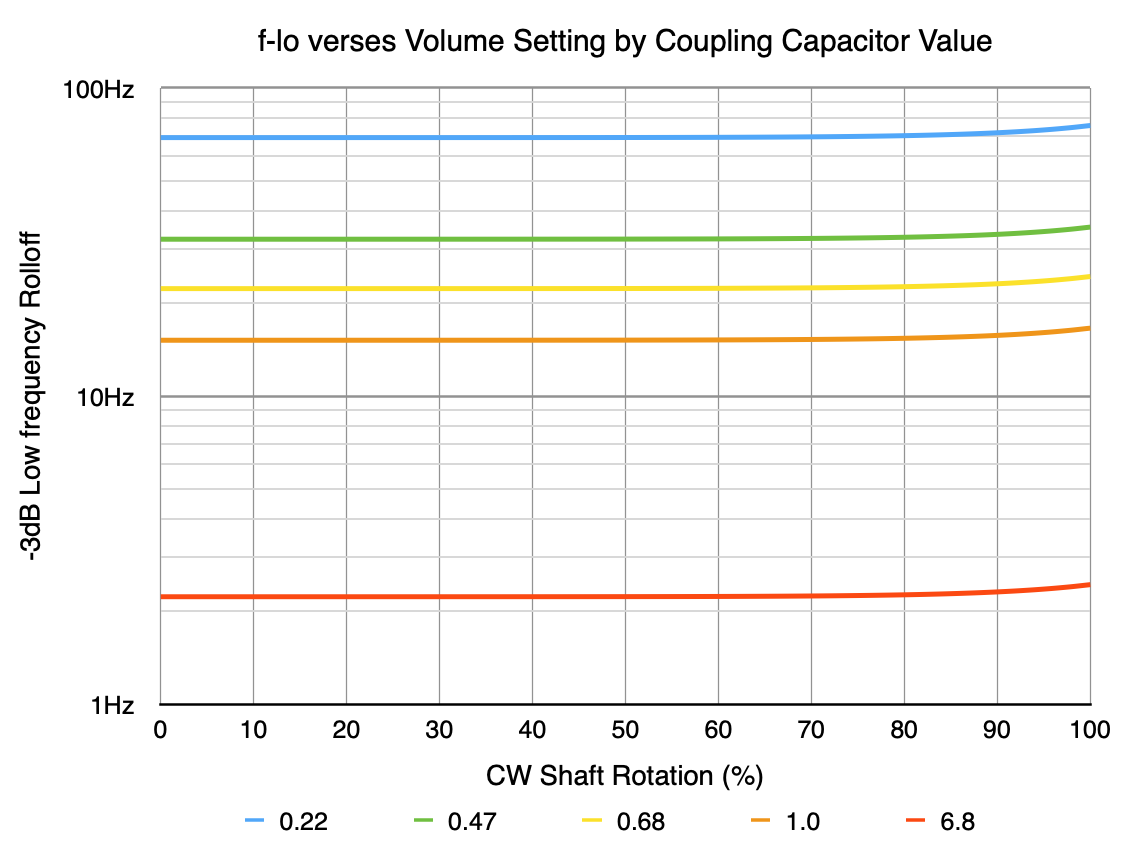
Going back to the example of the 12AU7 color preamp; Rsource=491Ω, Cc=1.0µf, Rload=10kΩ (worst case condition), and Ru+Rl=10kΩ (volume potentiometer value). I put these relations into a simple spread sheet with several different values of coupling capacitance. Here is the result.
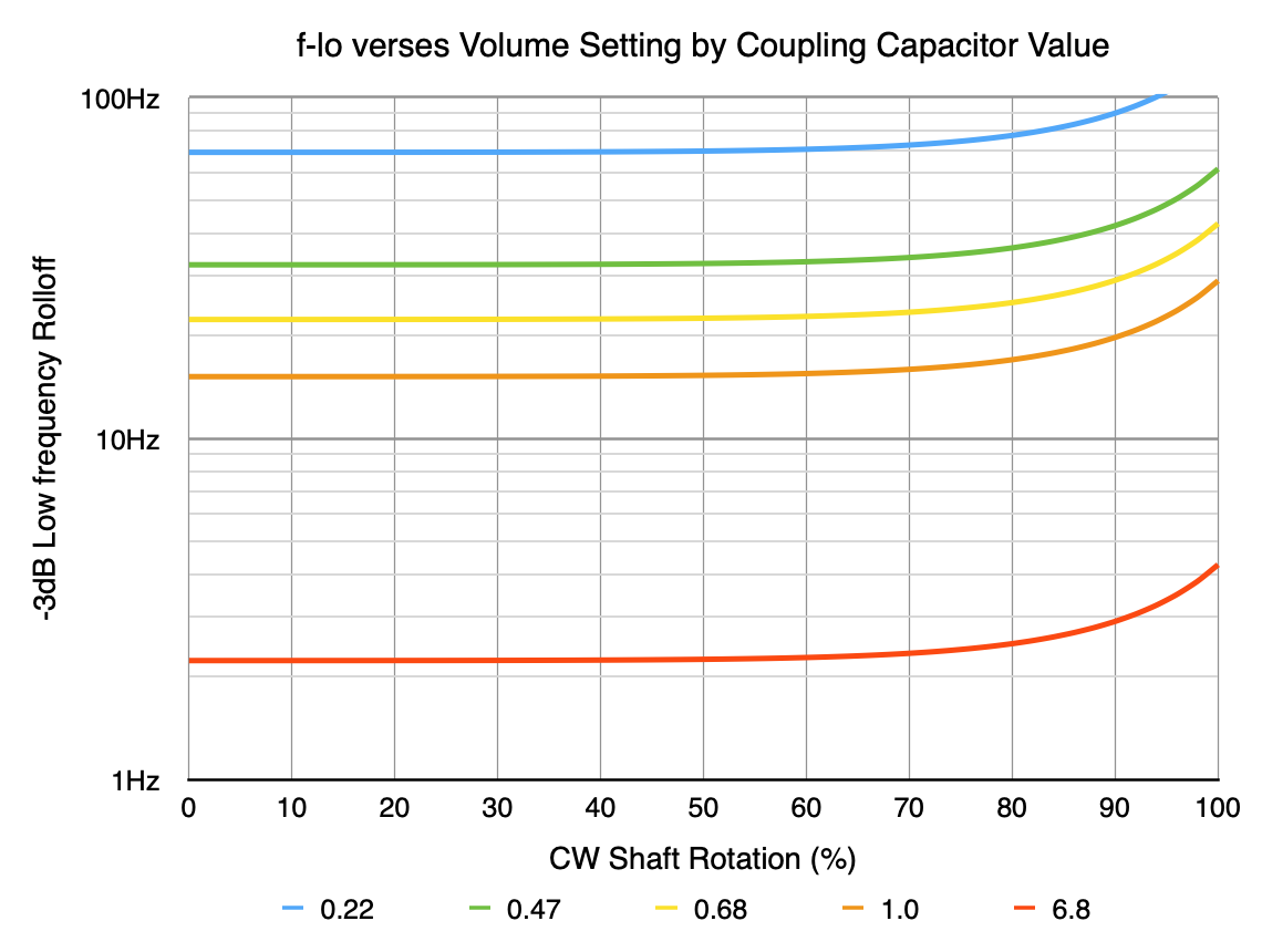
The line for the 1.0µf coupling capacitor starts at ≈15.2Hz at the zero volume setting and is relatively constant until about 60% volume setting. As the volume is increased from that setting the -3dB frequency rises to ≈20Hz at 90% volume setting, and tops out at 29Hz. The curves for other capacitor values follow similar trends. Please keep in mind this is with the absolute minimum load resistance.
If the load is increased to a more typical value for solid state amplifiers of 25kΩ (i.e. the input impedance of the amplifier on the output) then the curves flatten markedly. Here are those curves.
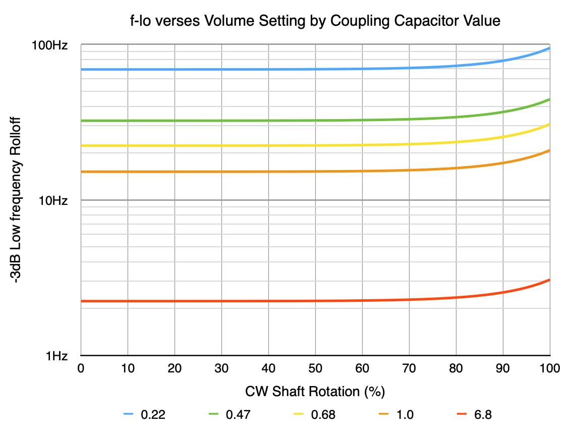
In this case, the curve for the 1.0µf coupling capacitor again starts at 15.2Hz at zero volume, but only rises to 17.3Hz at 90%, and tops out at 20.9Hz. If the load resistance increases to 100kΩ, the the effect is almost nonexistent.
In this case, the curve for the 1.0µf coupling capacitor again starts at 15.2Hz at zero volume, but only rises to 15.7Hz at 90%, and tops out at 16.6Hz. This is a change of only 1.4Hz between zero volume and full volume.
The other item to consider is the overall gain of the preamp. The 12AU7 color preamp was designed to be unity gain at the 50% volume setting. The full volume control range is approximately -20dB to +20dB. Given this wide (40dB) variable gain range, it is to be expected that the preamp would mostly be operated between about 30% and 70% volume setting. Even in the worst case scenario above with the 10kΩ amplifier input impedance, the low frequency shift between those settings is only 15.2Hz to 15.9Hz. This is imperceptible in any real world listening conditions.
I have included some other values of coupling capacitor values to show that the variation is similar regardless of capacitor value. I know that there are some people who think I design in too much low frequency rolloff in my designs. In that case, the builder could simply choose a slightly larger value and drive down the low end frequency accordingly. However, in any case, the variation with volume control setting is actually small even with the worst case amplifier input impedance, and is unlikely to show any impact under real world operating conditions.
These rolloff functions are “single pole” functions. This means there is only one frequency dependent item. In this case the coupling capacitor Cc. For such functions, raising one octave from the -3dB point, equates to a loss of only approximately 1dB. In every case with the 1µf coupling capacitor, this means the the -1dB point at lower volumes is only 2*15.2Hz or 30.4Hz. Most people simply don’t appreciate how little musical content is present below about 40Hz. And there is practically nothing below 30Hz. These frequencies simply don’t have that great an impact on perceived musical quality.
I hope that this puts to rest some of the latest concerns over the output volume control placement.
As always, questions and comments are welcome.
Hi Matt,
What is the effect of replacing the 10k volume pot at the output with a 50 k or a 100k pot?
When the value of the potentiometer is increased, it increases the output impedance. So it increases the loading on the capacitor. This makes the frequency dependent portion of the curves essentially disappear. However, since it raises the total output impedance it will increase coupling loss if you attempt to drive a lower impedance load (i.e. R-load). There is a definite tradeoff involved.
I know it was a lot of work, but I appreciate having this info in print. It’s tone reminds me of what you wrote about in the “The Quest for 20Hz Roll Off” post. Thanks!
Pingback: About that Volume Control | Cascade Tubes