
While I was preparing to begin assembly of the vacuum tube circuits for the Source Selector Unit, I was quickly going over the design and pulling components. And this is when I became aware of a little problem with the buffer circuit.
The problem has to do with the operating point of the cathode follower and the ratings of the 12AU7 tube. Specifically it has to do with the Heater-Cathode voltage limit for the heater negative voltage with respect to cathode. Here is the operable section of the 12AU7 data sheet.
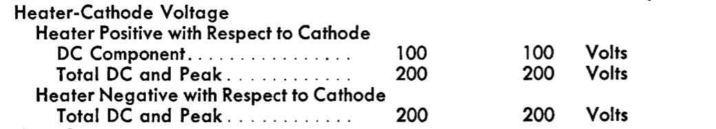
For this tube the limit is 200v for DC plus peak AC. The reason for such limits is simple in unipotential cathode tubes. There is insulation on the heater which prevents electrical contact between the heater and the cathode. This is what allows the use of common filament supplies across different vacuum tubes. But that insulation has its limits. In operation, the filament raises the cathode to between 1000K and 1300K. The insulation has to maintain its nonconductive properties at this elevated temperature across all the operating voltages of the tube. But if the insulator is made thicker to handle higher voltages at this elevated temperature, then it takes more current to get the cathode up to temperature. Obviously, some design trade offs are involved and this is from where the limits come.
So I took at look at the design parameters for the buffer cathode follower. Here is that section of the original schematic with the salient node voltages annotated.
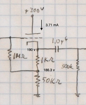
Here we can see that, at DC with no signal present, the cathode voltage is already at 190V. If the gain control was turned up, it is conceivable that the peak AC value through the buffer could exceed 10V. Designing with no or negative margin is a situation I strive to avoid.
Now there are a couple of ways to deal with this situation. One is that I could elevate the heater voltage by some nominal voltage. Let’s assume 50V for discussion. This would lower the heater to cathode voltage to 140v. It is virtually impossible to get the peak AC output through the stage to 60v, so this would correct the problem. But it would also leave the heater in the gain stage about 43v above the cathode. Now according to the data sheet this is acceptable.
Acceptable, however, not optimal. Whenever possible I like to keep heater voltages as close to ground referenced as possible. This limits stresses in the power transformer and is more in line with how the tubes were designed to operate. I have also found that the best gain stage noise performance is generally achieved with a ground reference heater. In fact, the low noise specifications of the 12AX7/7052 tubes specifically require a ground referenced heater for noise measurement.
So the other way to correct this was to increase the bias point of the buffer. So this is what I did. By simply changing the cathode follower bias resistor I increased margin and even slightly improved the performance of the buffer. Here is the new cathode follower circuit as recorded in my design notebook.
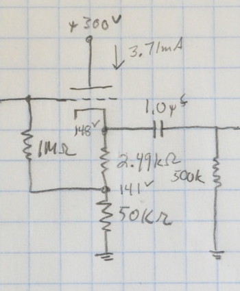
Note that the cathode follower current above is from the old bias point. The current at the new bias point is 2.82mA.
This design point increases the DC margin from 5% to 26% and still allows the heaters to be ground referenced. To get to the tube limit the AC signal through the buffer would have to be 52V peak or 36.8v-rms. This would require a very hot input to the preamp and having the gain control turned all the way up. And it would still be just marginally at maximum specification.
This solution also has the added benefit of being simpler to implement. I can change the value of one resistor and avoid having to have a separate voltage divider on the B+ tied to the heater center tap. And my gain stages operate with lower noise.
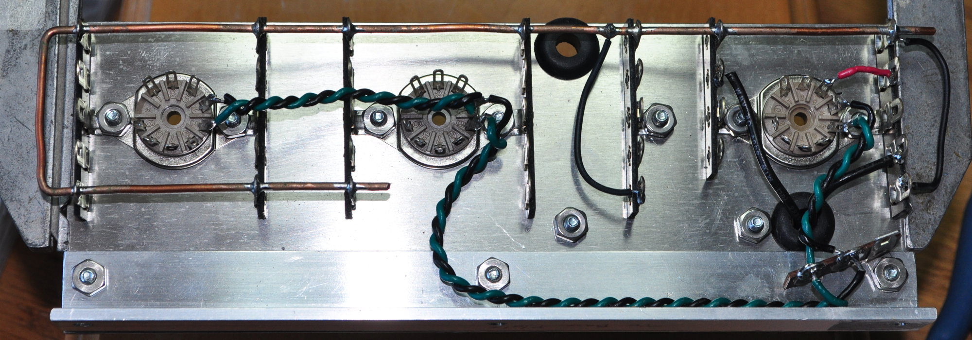
Now that I’ve tackled this problem I can get back to assembly. Currently there isn’t much on the assembly except the heater wiring and the choke connections.
I’m glad I caught this before I got any farther on the wiring. Changing two resistors (one for each channel) is really the simplest possible fix.
As always, questions and comments are welcome.
Changing one resistor sounds like a “For the want of a nail” proverb. Glad it was an easy fix!
Actually verifying the design (down to the 10kΩ amplifier load) took far more time than choosing the new bias point and resistor. But it’s done now.
Nice catch 👏
Thanks. 🙂