
Now that the Source Selection Preamp writeup is complete, I took a little time today to prepare for another effort.
Here is the unit on which I was working.
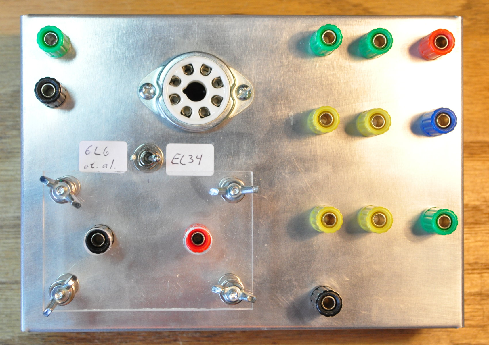
Astute readers will recognize this as the jig I built to perform the 6L6 UL Optimization study. However, it’s undergone a little change.
This jig was originally built to work with power pentodes with 7AC and similar base pinouts. These include the 6L6, 6V6, 6W6, 6Y6, and similar tubes. In the 7AC pinout, pin 1 can be either an internal shield or not connected. So on the jig I left pin 1 open. But for this new project I need something different.
I want to start work with an EL34/6AC7 power tube. The EL34 has a 8ET pinout which is virtually identical to the 7AC with one exception. In the 8ET pinout, the suppressor grid is not directly tied to the cathode (as in the 7AC) but is instead brought out to pin 1. So the addition is this little switch.
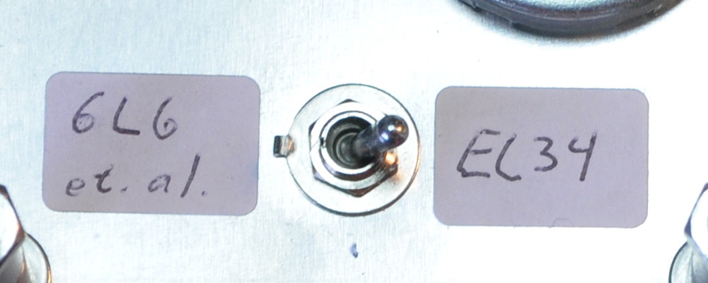
With the switch in the 6L6 position, pint 1 is left open. In the EL34 position, pin 1 is tied to pin 8 (i.e. the cathode connection) which is the way EL34s are generally run in audio frequency power amplifiers.
Now I just need to start reviewing data sheets and curve families to see where I want to start with this new optimization study. I publish more as I proceed.
As always, questions and comments are welcome.
Matt,
Any chance for a push-pull EL-34 amp?
A pair of those bad boys can really “rock out”
Not likely. I’m not much for PP topologies.
But if I did one, it would probably be PP 6AQ5s in UL (biased to maximum class-A) with a 12AU7 gain stage and concertina phase splitter. That’s the one PP to which I’ve given serious thought in the past. But there would be a fair level of prototyping and testing involved.
Another interesting PP concept I have seen is running the output stage as a class A long tailed pair (Oddwatt, et. al.). No phase inverter required in this setup. Food for thought.
Looking forward to it!
Hi Matt,
What is the effect of exceeding the recommended max screen grid voltage on the distortion of a tube with UL tap ? Will you be looking at this ?
The reason i ask is that I built a 12BYA SE amp with UL tap recently. The data sheet says screen grid is 190v max. But i am at 207v. Screen resistor @1.2K. Distortion is 0.8% at 1KHz. Will getting the screen voltage within the recommended value increase the distortion on the amp ? The amp sounds great but with high distortion at the low end but all second harmonics similar to what you observe on your 6CY7.
The screen voltage maximum is there for pentode operation. It places a total limit on the operation of the tube. UL operation is a little bit different. The real physical limitation is the screen power dissipation.
In a UL design, the quiescent conditions ALWAYS have the screen at a slightly higher voltage than the plate. But if the product of the screen current and screen voltage (measured screen to cathode) is less than the screen dissipation limit it’s generally okay. For the 12BY7A the screen dissipation limit is 1.1W. So in your amplifier, with the screen at 207V, the current needs to be less than 5.3mA (1.1W/207V). Since you have a screen resistor, just measure the voltage across the 1.2KΩ resistor and if it’s less than about 6.3V, the screen dissipation is within limits.
My experience with UL designs is that, in general, the screen dissipation is almost always well within power limits. This is why I virtually never use screen resistors in my UL power stage designs. In any event, it’s pretty easy to check.
Are you planning to test running bias voltage to the tubes the way they do in guitar amps or is it a more strict UL tap design?
This study will be done with audio reproduction in mind so it will be a UL study. I’m not a fan of pentode operation for music reproduction.
I know earlier you were thinking about experimenting with the KT88. Has the EL34 taken priority over it for optimization studies?
Yes.
The KT-88 is just another, and larger, beam power tube. But the EL-34 is an honest to goodness power pentode with an actual suppressor grid. I’m interested in seeing how the tube’s response differs from tubes utilizing beam forming plates (and the resultant virtual cathode field point). Also, the higher average screen current of the suppressor pentode (verses the beam power tube) will likely have some effect on the output transformer UL tap and primary voltage distribution.
I haven’t attempted any field modeling of the different structures, but some quick “back of the envelope” calculations say that the response should be different. At a minimum a much larger shift between static and dynamic operating point at higher plate voltage swings. This could manifest as a higher harmonic distortion which does not follow the power proportionality rule which is roughly applicable in UL operation of BPTs.
I think it will be interesting experiment.