
One of the risks of becoming too familiar with vacuum tube electronics is that it’s easy to become a little careless when working around high voltages. And because of this learned carelessness, sometimes we don’t take as many precautions as we should. Especially when prototyping.
For those wondering, I haven’t dropped off the face of the Earth for the last month. January was cold, dark, and rainy in these parts and I reacted to such conditions as I usually do. I retreated to the leather recliner in my office and poured myself into reading. In the last month I’ve read eight novels, three full length nonfiction books, a handful of technical papers, and about a hundred web articles. But I also found a little time to prototype a power supply using the Edcor XPWR011 800vct power transformer. And it’s this physical prototype that prompted this post.
When prototypes are assembled at all, they have a tendency to be rushed. It’s not the final circuit and in most cases the prototype is just to ensure the circuit is functional or just to check a parameter. So builders tend to take shortcuts. They use loose wiring, solder-less bread boards, and even alligator clip leads. All these things can work, but each one of them greatly increases the risk to both your circuit and yourself. Shorts can happen in an instant destroying components. Intermittent connections can cause incorrect readings and persistent frustration. And all those exposed conductors pose a real electrocution hazard.
My Prototype
I turn now to my specific situation. I have an Edcor power transformer which I purchased about 10 years ago for an amp which I never built. It is an Edcor XPWR011 – 800V@200mA CT, 6.3V@5A CT, & 5V@3A power transformer. The full high voltage primary is rated 800V at load and the unloaded voltage is closer to 850V. I have two amplifier designs for which I might like to use this transformer. Both require different B+ voltages. I needed to prototype a power supply using this transformer to see exactly how much voltage I could achieve under load. I am also very cognizant of how quickly this power transformer could permanently change my life (or end it) if misused.
So I decided that I would use a more robust approach to prototype construction. Nowhere would I rely on anything that even looked like an alligator clip, And most of the high voltage terminals, while not completely enclosed, would at least be both secure and isolated against careless touching. This meant a good baseplate, components rigidly attached, and electrical connections made with terminal strips and connectors. This might seem like overkill but it actually took very little time and effort. Here is the prototype sitting on my work desk.
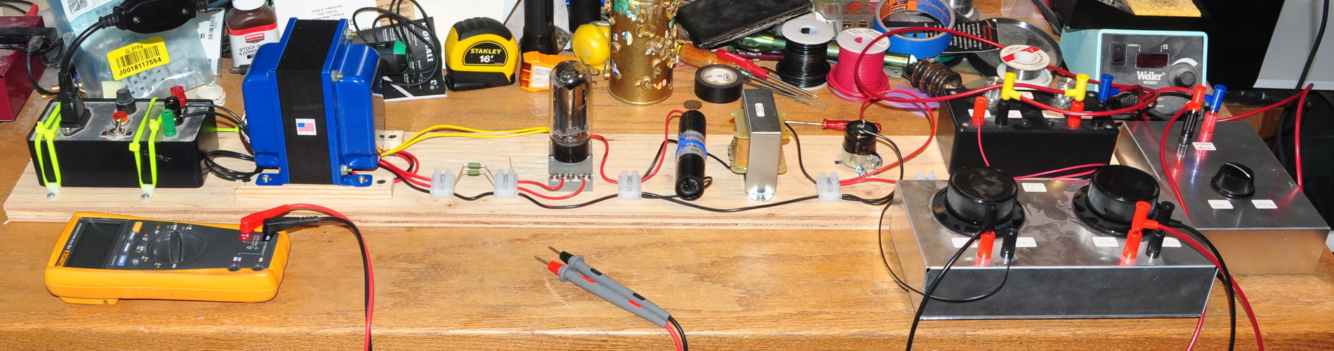
From left to right are the mains power control module (I’ve talked about this before), the power transformer, secondary series resistors, rectifier tube, main reservoir capacitor, first stage LC filter, and various high power load boxes. I would like to add that there is nothing special about the linear layout of the prototype. Mine is laid out in this fashion because this was the first piece of plywood I picked up off the scrap pile in my workshop. That’s the only reason. If the first piece I grabbed was square, that’s what I would have used. The actual layout is much less important than the manner in which the layout is achieved. Let me explain.
Features of a “Safe” High Voltage Prototype
Mains Power Control – I always want a secure positive way to control the application of mains power to my prototypes. The box on the left contains an IEC connector, fuse, indicator light, and toggle switch. The hot, neutral, and ground connections are brought out to three binding posts so I can make positive connections to the circuit. And the three wire mains cord allows the exposed metal to be connected to Earth ground.
You can see in this picture that I’ve secured the box to the board so nothing can move if the cord gets yanked on for some reason.
Secured Power Transformer – This power transformer weighs a fair amount. Now I could have simply set it on the board upside down but I wanted it secure. All this securing items is to help prevent forces inadvertently being applied to leads and wiring. So the transformer is securely screwed down. You’ll also notice that I have properly terminated the unused 6.3V winding using some pieces of shrink tubing and a cable tie. This helps prevent inadvertent contact to that winding while testing.
Enclosed Terminal Strips – All connections not made to binding posts are made with European style terminal blocks. I like these for prototyping because all the conductive parts are surrounded by plastic so it’s very difficult to get a shock from one of these. These are secured to the board with simple #6 wood screws. This may seem like overkill to some people but it’s a simple step that helps make everything secure, easy to see, and easy to follow. I purchased a bag of 10 of these three position terminal strips for less than six dollars. That’s a good investment in safety.
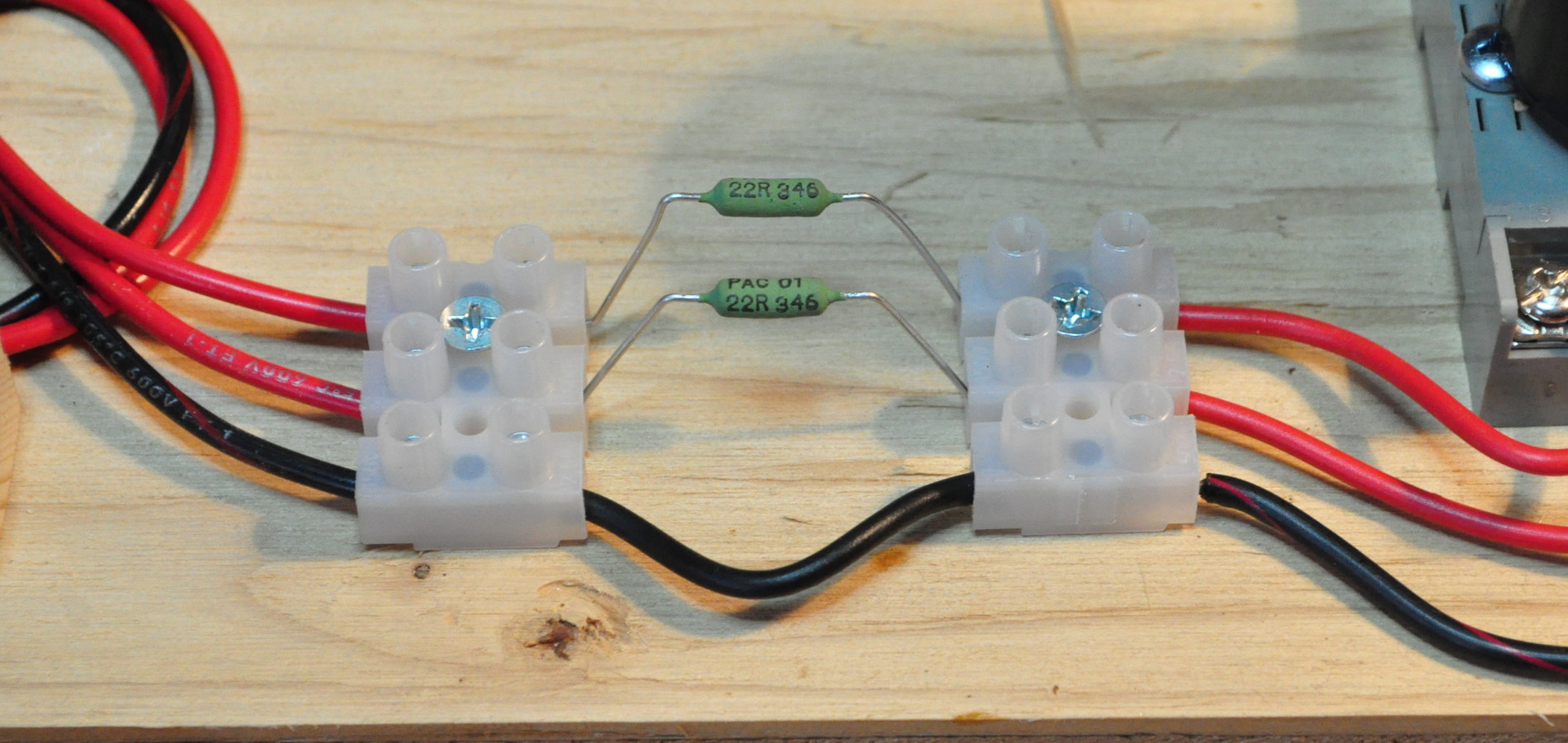
Because of the voltages on the secondary, the rectifier needs a minimum value of plate resistance. A couple of these terminal blocks make the installation (and swapping) of these resistors a simple matter while keeping all the connections secure.
There is 800 VRMS between these two resistors in operation. This is probably the most dangerous point in the entire prototype. Just something to keep in mind during testing.
Securely Mounted Vacuum Tubes – Here I have utilized a simple octal DIN socket to mount the 5AU4 rectifier. These sockets typically have screw terminals for nice secure connections.
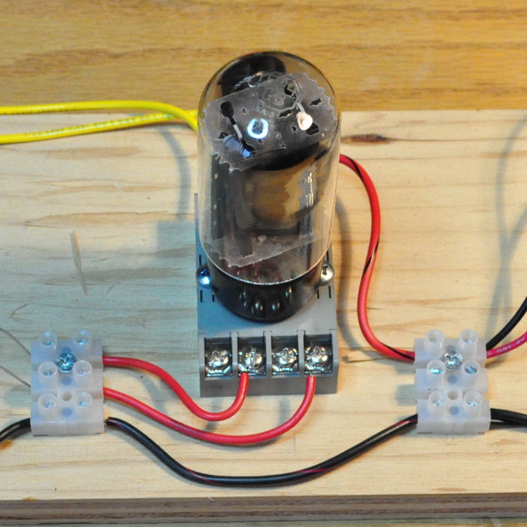
These sockets allow for rigid connections and easy change out of rectifiers without rewiring. This socket is held to the mounting board with a couple of screws through existing holes.
Securely Mounted Filter Components – The rest of the prototype components are all securely mounted and interconnected with terminal strips.
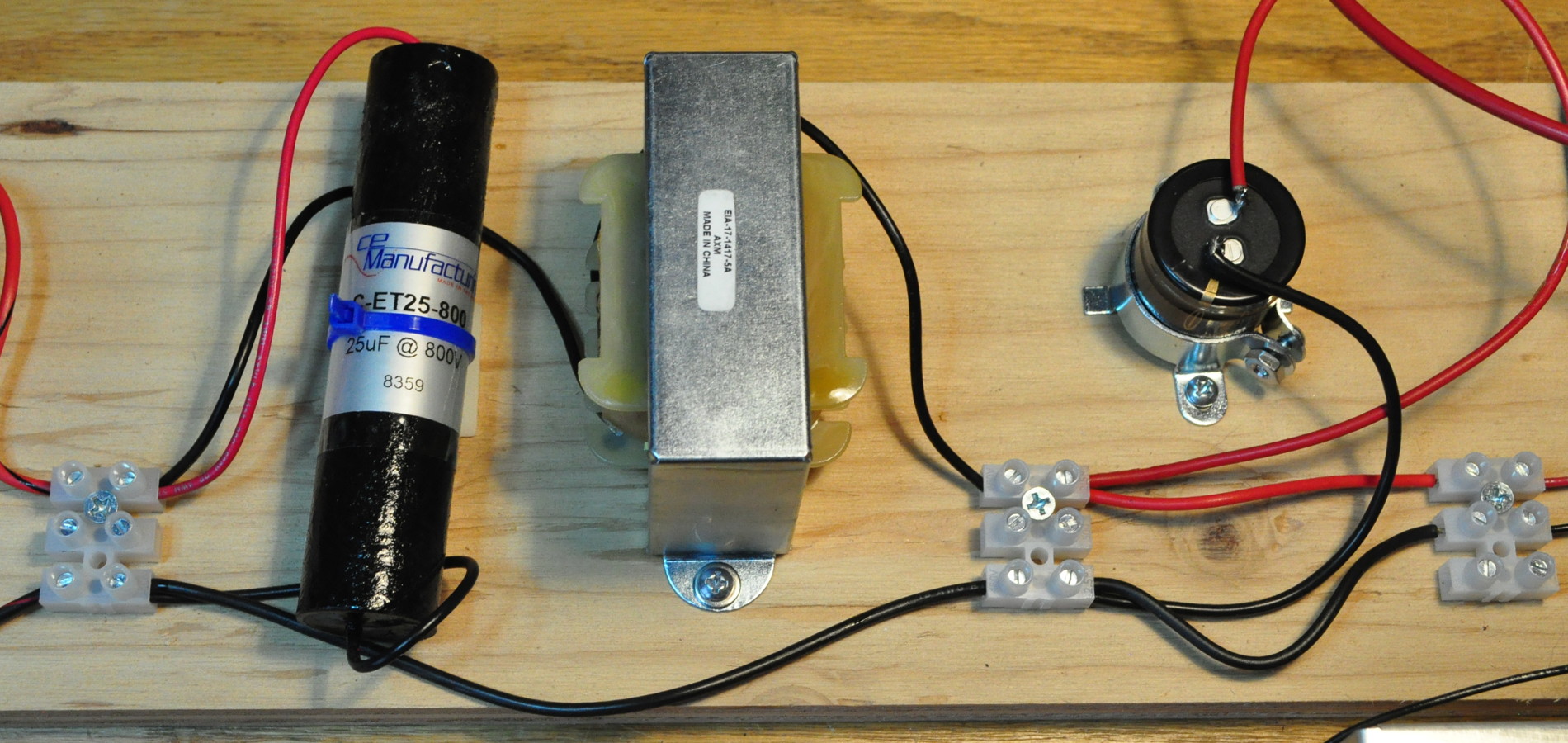
Here is the main reservoir capacitor (25µf@800V) and the first LC filter stage (6H / 100µf@630V). For each component I have ensured that it can’t be knocked out of position or moved placing tension on any connection.
Safely Configured High Power Loads – For the load on this supply I have utilized high power rheostats mounted in aluminum enclosures. These are part of my standard set of test equipment.
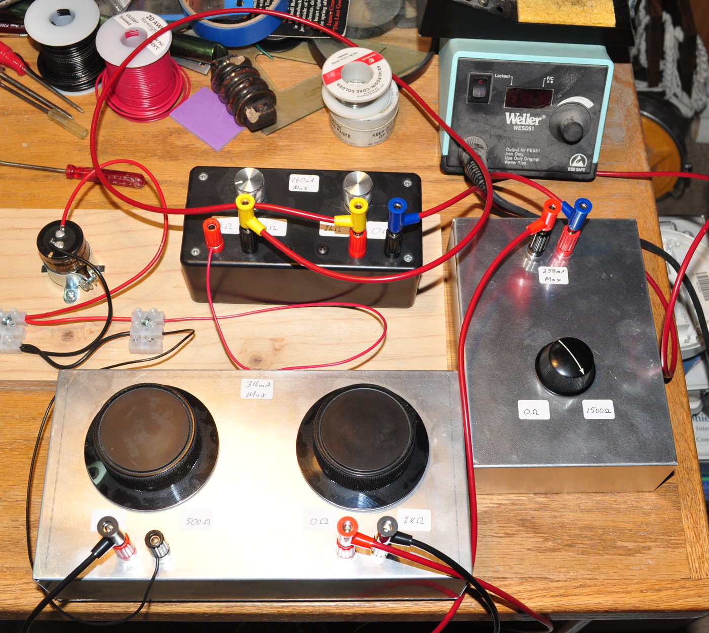
Due to the voltage I ended up having to rig five loads in series. And I did resort to test leads with banana plugs for the load boxes but these connections are relatively secure and load adjustments are made by simply turning controls.
Excessive?
I know now that some people will immediately accuse me of excessive caution and “over doing” a simple power supply prototype. Obviously I disagree. This assembly cost me approximately two additional hours of time and effort. But the result is a well constructed prototype that allows me to investigate how the power transformer works with different loads and different rectifiers in a number of different configurations. At no time during testing, from the initial power on, to taking readings on the load, did I ever have any concerns or apprehensions with this prototype power supply.
When working with people on electrical projects I often witness what I call, The Power-On Flinch. It’s that little flinch or jump when the main power switch is initially thrown and power is applied. Like they are expecting something to short, spark, or explode. My thought is always the same: If you don’t trust your wiring, why are you applying power? If your prototype is properly constructed, and you’ve properly checked the components and connections, there should be no flinching. If you do flinch, perhaps you should spend a little more time on your project before throwing that switch.
As always questions and comments are welcome.
Definitely the correct way to do it! Every part secure with lots of space, color coded wiring, terminal blocks. Easy to follow the circuit without a schematic.
Pingback: Gremlins in the Machine | Cascade Tubes
Thanks for the picture. The layout on the plywood reminds me of the very old radios that would have all of the components in order from battery to horn on the breadboard.
Looking forward to seeing your test results. I am sure that the data will help you design the optimal circuit for such a large PS. Hopefully, February will be a little warmer in your area.