
Well, all the data for the aforementioned optimization is collected and in the computer. I’ve been chewing on the data and my notes for the last couple of hours and it’s safe to say, there is a lot more here than first meets the eye.
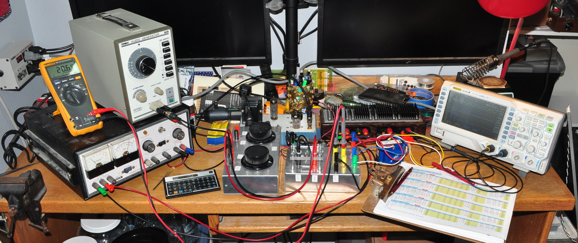
Here’s how my desk looked when I just finished taking all the data.
Some of the data series were taken multiple times. This was simply because the data is such a departure from what I recorded during the 6V6 and 6L6 optimizations. Some looks mostly like I expected. For example, here is the top level plot of maximum RMS power out verses bias voltage for five different plate voltages.
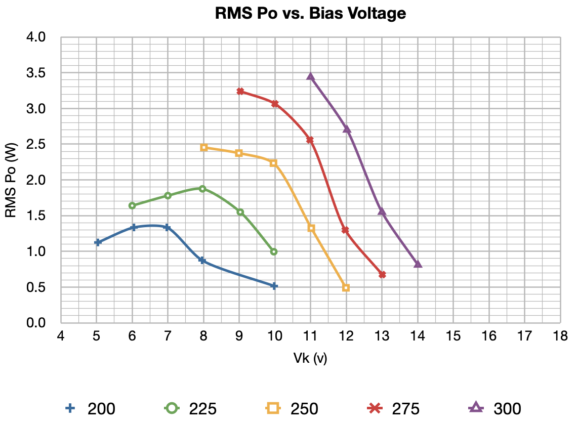
These curves are not wildly unexpected but I would have expected the higher plate voltage curves to be more horizontal. However, some of the other series data for dissipations and harmonic distortion will take some time to get my head around.
The only conclusion I can comfortably draw right now is that the EL84 should never be operated at a plate voltage of 300V. I think a plate voltage of about 275v is the highest I would ever run this tube. The behavior at Vp=300v seems to indicate that the suppressor grid is not functioning properly at this plate voltage level.
I’ll have to chew on this entire data set for a while before I can begin to draw any firm conclusions, I may also try a few listening tests at various operating points as well. Just to see if some of my suspicions are borne out in the actual operation.
As always, questions and comments are welcome.
Forgot (gettin’ “up there 😊”) – Are the power outputs you measured in your test at some particular distortion level, misshapen sine wave, clipping, etc.?
I’ve tried to use a measured distortion level to predict the top and I’m not wild about that approach. What I do is literally just look at the onscreen waveform and compare the input and output waveforms. I lay them on top of each other on the oscilloscope so I can easily see both clipping and compression. When the two waveforms begin to diverge I call the top. Although in some of this data I continued to take data beyond this because of some high 2nd harmonic distortion numbers.
I do that too. Quick check for fidelity.
Real world observation – most commercially made 6BQ5/EL84 amps I have seen and repaired over the years ran the plate and screen at 250VDC +/- a bit. Based on the data sheets I have, 300VDC is an absolute maximum value.
Is this with ultralinear like your previous tests? The EL84 is such a popular tube in all circuit types though it seems like I usually see SE using it in triode the most.
I am currently listening to what I have been told is an el84 variant made by GEC, the cv4062 in a SE pentode amp. I don’t know the precise numbers other than the screen is run with a regulated 265v. The b+ is probably around 300v. It is an amp made by Dennis Had called the KT88 Firebottle. Sounds quite nice being driven by a GEC b36. Not super useful info I know but thought I’d share. You don’t see many amps like this.
Yes, this test is in UL mode with a 40% screen tap. I’ll be talking about that more in the writeup because of the way that the power stage responded. As for the operating voltages, as I said above, I saw behavior that leads me to believe that at the upper plate voltage limit (along with the high screen voltage) the suppressor grid was getting overwhelmed. I’ll be discussing this a lot more in the full writeup.