
Lately I’ve been looking at a project that’s been sitting on the back burner for quite a while. It’s a stereo power amp for which the 6EM7 Vertical amp chassis was a proof of concept. This amp uses an 807 tetrode in a triode strapped configuration. Now the one thing that I didn’t care for in the load line design was the level of distortion. From the load line paper design, distortion peaked at around 8% at 4.31W output, yielding a Ds of 1.8%/W. This is larger than I generally like in my amps. Then I had an idea.
If I didn’t bypass the cathode resistor on the output stage, the negative feedback (i.e. cathode degeneration) would correct for some of the distortion. My only concern was that in these tetrodes, even when triode strapped, µ tends to run high. With the cathode unbypassed, the output impedance seen by the load transformer is increased by µ+1 times the cathode resistor. In this case it increased the impedance by over 6kΩ. I was very concerned about what this would do to the low end roll off frequency. I didn’t want to go to the trouble of designing and building a triode amp and have it lack proper bass support.
Clearly it was time for some prototyping work. Now what I really wanted to do was compare the bypassed and unbypassed configurations. So I came up with the following circuit.
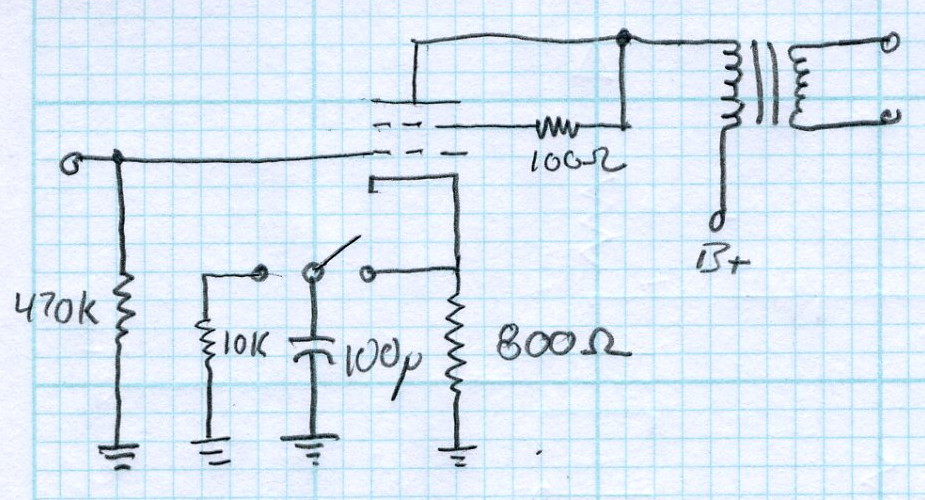
This would allow me to simply flip a switch and go from bypassed to unbypassed configuration making it simple to test the circuit in both configurations. Here is the prototype I built.
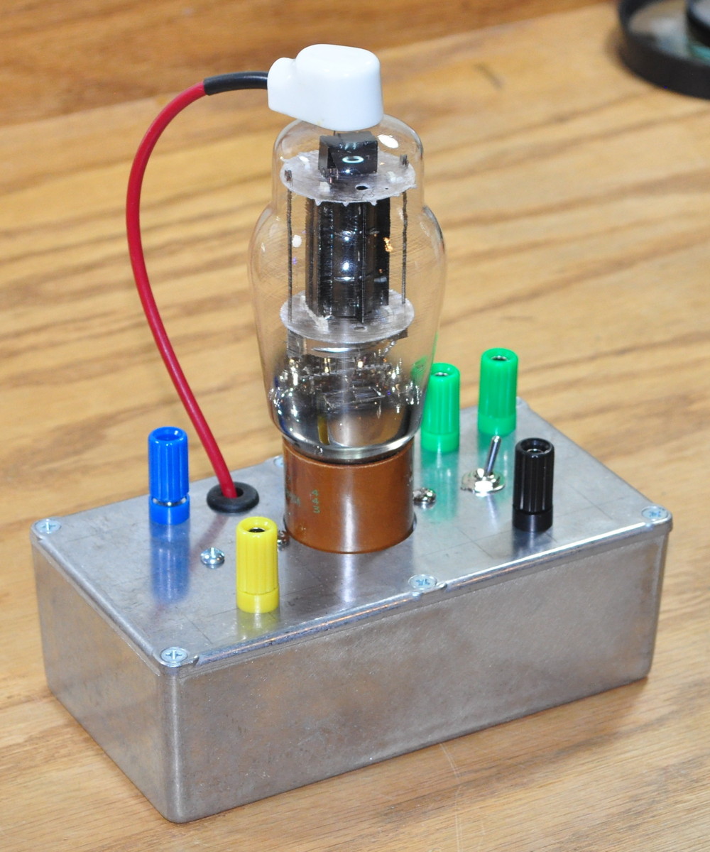
It is build on a Bud Industries CU-476 die cast aluminum box. The green binding posts are for the filament, black is ground, blue is the plate connection to the transformer, and yellow is the signal drive input. Once I had my prototype power stage, I set about taking some data. Here is my test setup.
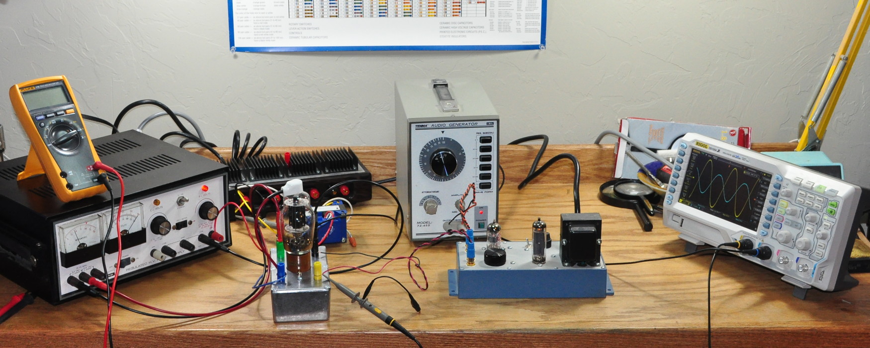
I have a signal generator feeding a 4S preamp with a 12AX7 to drive the power stage. I used an Edcor GXSE10-8-5K output transformer connected to an 8Ω dummy speaker load. Here’s a close up of the power stage in operation.

I have monitoring on the signal input to the power stage and the speaker leads of the output transformer. This allows me to see how the performance changes including the transformer effects.
The first test I ran was to check the low end rolloff in both configurations. I start at 1000Hz with an output power of 1W into the speaker load. Then I start to reduce the frequency and record the response. So here is a plot of the magnitude data comparing the two configurations.
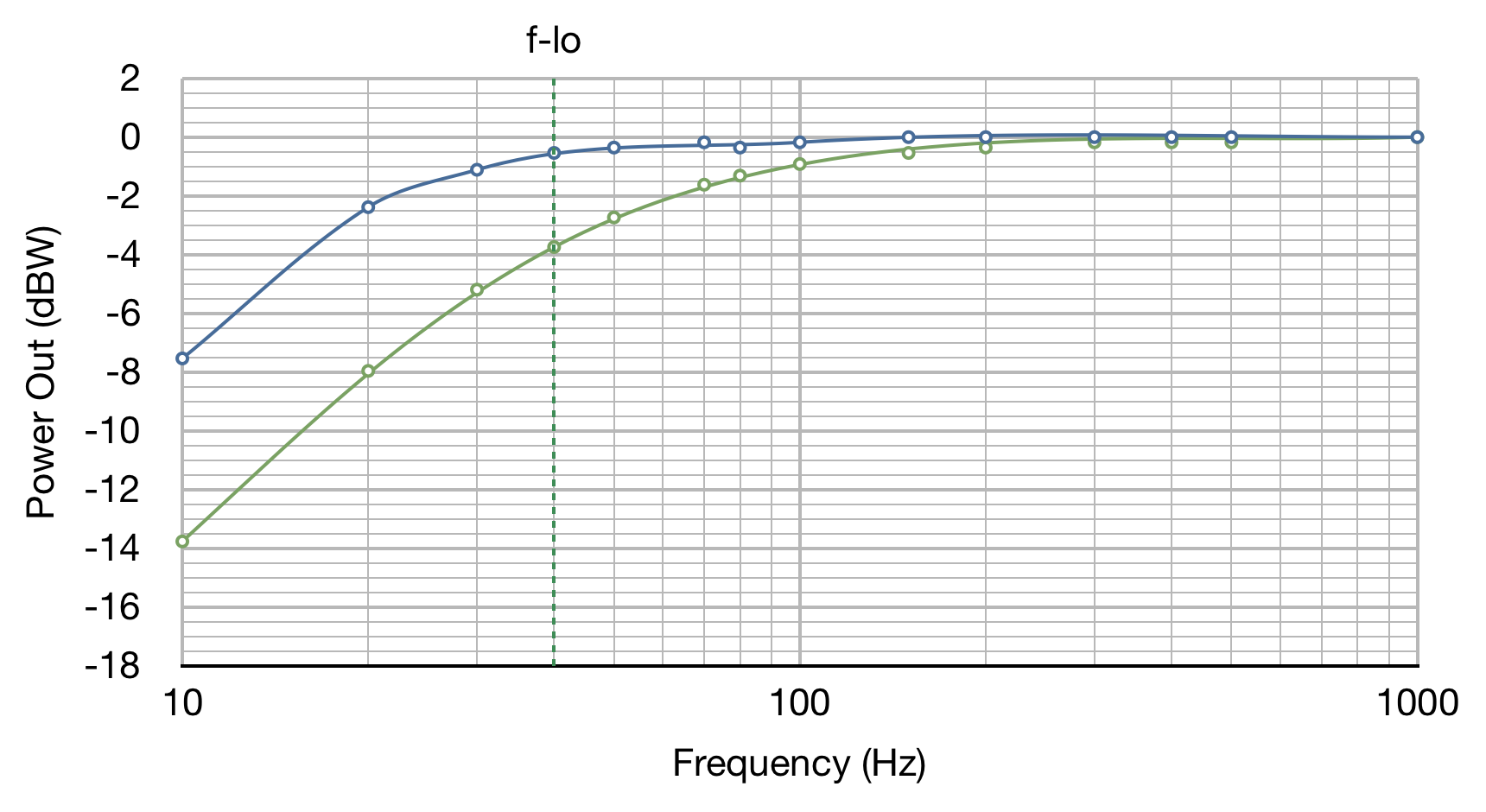
Here the blue line is the bypassed cathode response and the green line is the unbypassed cathode response. The dotted line labeled f-lo is the lower bound of the output transformer frequency specification. Clearly my concern was warranted.
With the cathode bypassed, the power stage response covers the low end very well. At the transformer lower specification it is only down by about 1/2 a dB and even at 20Hz, it is only down by about 2.4dB. In contrast, the unbypassed configuration is off by 3.7dB at the lower transformer specification and is down a full 8dB at 20Hz. If I really want the bass support, I guess I’ll use bypassed cathode configuration.
Now this could be then end of the story, however I noticed something very interesting as I was taking the data.
The transformer I was using is an Edcor GXSE series unit rated for a frequency response of 40Hz to 18kHz. Now what generally happens at low frequency is that even though the response is still there, as was the case in the bypassed cathode configuration, the distortion in the waveform begins to increase. So when I got down to 20Hz in the bypassed case, the waveform had visibly significant distortion. However, what I noticed in the unbypassed configuration was that at 20Hz, the waveform distortion was far lower. This called for further investigation.
So the first thing I did was a quick distortion measurement at 20Hz for both configurations. I measured the 2nd, 3rd, and 4th harmonics and used this data to calculate the THD numbers for each case. I took these initial measurements at some convenient points but unfortunately didn’t pay a lot of attention to how hard I was pushing the stage. Here is the initial data.
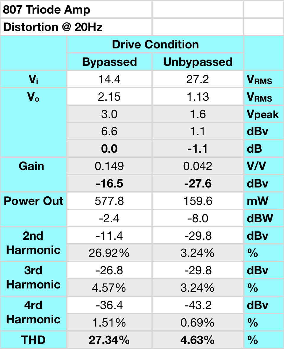
By the time the bypassed configuration gets down to 20Hz, the distortion (particularly the 2nd harmonic distortion) has really become extreme. In contrast, the unbypassed configuration get a full octave below the transformer specification with a very respectable distortion number. Since this was just some spot check data, I decided to investigate further.
I decided to take distortion data for both configurations in two ways. First, I would take the distortion numbers while keeping the output power constant. Then I would take the data again and set the output power at midband but allow it to fall off with frequency. I reasoned that the first data set would allow me to compare the relative improvements due to the negative feedback (technically cathode degeneration) at similar transformer power and hence core magnetization levels. And the second set of data would tell me more about how the response would look in an amplifier in use.
So here is a plot of the first set of data. In this data set, the output power level was maintained at 1/2W across all frequencies. This data exaggerates the distortion at low frequencies but allows direct inferences to be made about core magnetization. In this plot, solid lines represent the bypassed cathode configuration and dashed lines the unbypassed configuration. The lines are also color coded. Blue is Total Harmonic Distortion, red is 2nd harmonic distortion, green is 3rd harmonic distortion, and orange is 4th harmonic distortion.
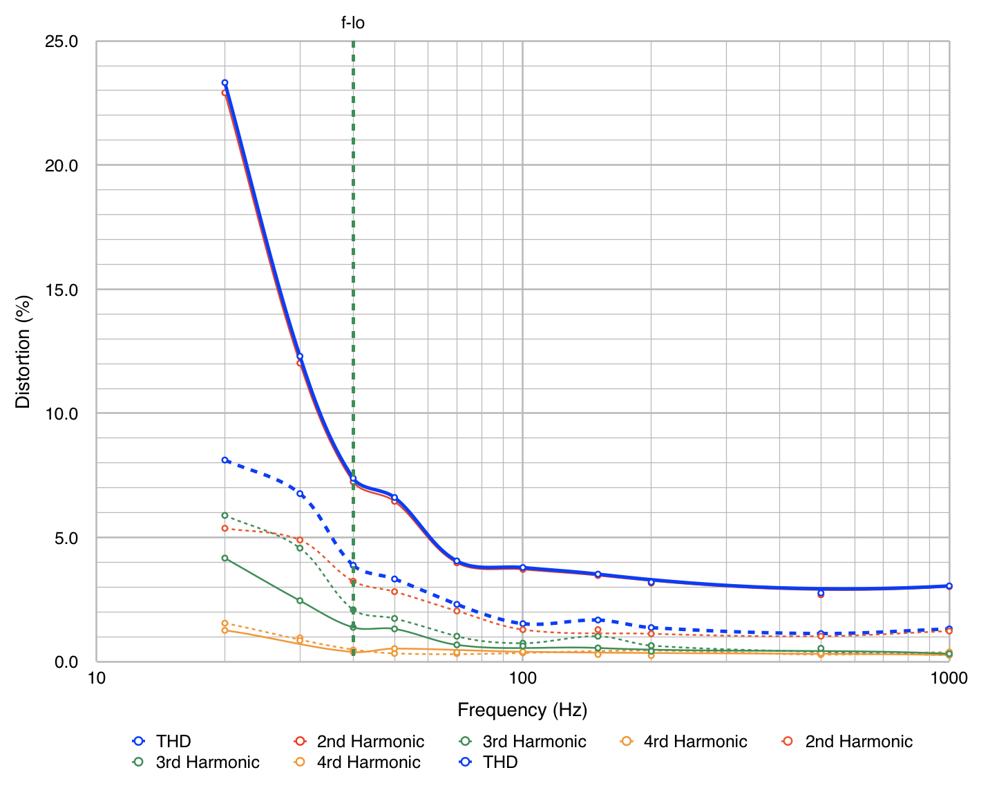
Some interesting things become apparent from this plot.The first is that the feedback is having virtually no impact on the 4th harmonic levels. In both configurations they are very similar. This may simply be the result of the frequency of this component being four times the fundamental and thus, in the performance band of the transformer. The next point illuminated is the relationship between the 2nd and 3rd harmonics. In the bypassed case, the 2nd harmonic clearly dominates all the way down to 20Hz. But in the unbypassed case neither the 2nd or 3rd harmonic dominates. This characteristic will make the amplifiers sound very different to the ear. But we need to know what happens in the other case where power is allowed to follow the natural response of the amplifier.
Here is the data taken for the second case. in this instance output power was set at 1/2W at 1000Hz and then allowed to roll off with frequency. I have also separated the data into two plots for clarity.
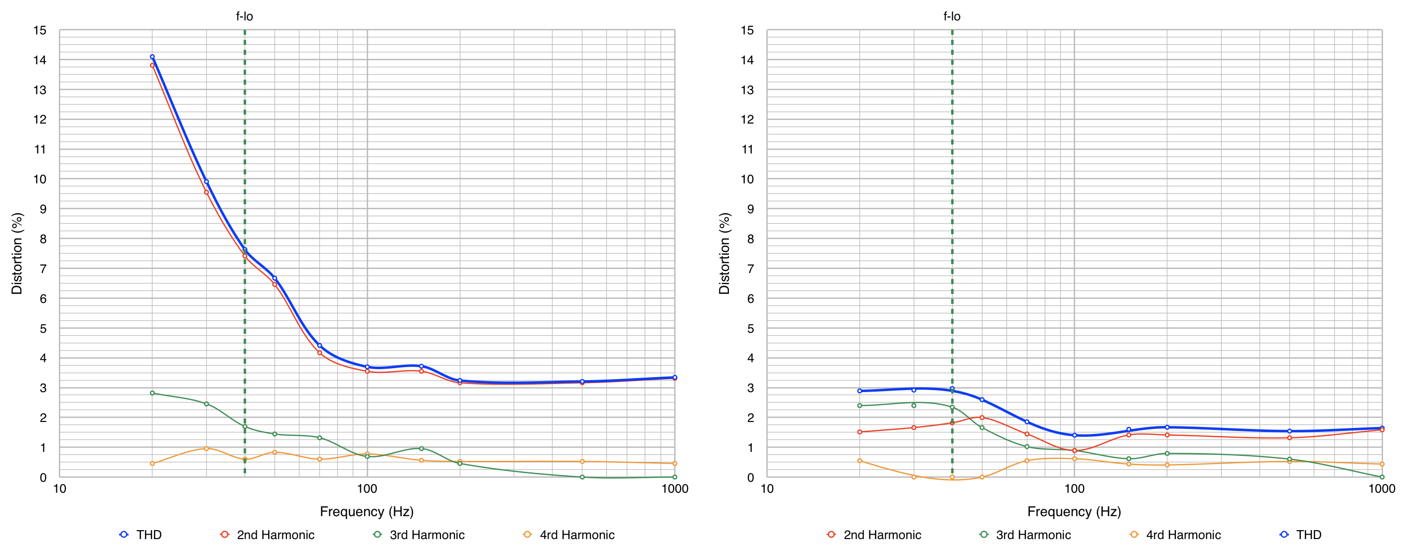
Here I kept the y-axis scales the same to aid in comparison. The first thing to note is that the distortion levels are much lower. This is as expected because output power is being allowed to fall with the natural response of the stage. The other very interesting item to note is that the 3rd and 4th harmonics are very similar in both cases. Where the differences lie is with the 2nd harmonic response.
In the bypassed case, the 2nd harmonic is the dominant distortion and this will heavily color the low frequency response of any amplifier. In the unbypassed case, the 2nd harmonic is much lower, and it falls below the third harmonic as frequency drops. This will produce a discordant response at low frequency which will strain the ear. Even though the THD numbers for the unbypassed case are lower (almost 50% lower at midband) the harmonic structure at low frequencies is highly undesirable. The dominant choral harmonic in the bypassed case will yield a amplifier response that, while not technically accurate, is very pleasant. Whereas the unbypassed case will yield a discordant lower frequency response that is unpleasant and harsh.
So, here is a lesson in tradeoffs. Design the power stage for higher overall distortion but with pleasant overtones or design for lower distortion and more technically accurate response but live with that unpleasant odd order overtone? Well, I think I’ll go for the better sounding power stage; bypassed it is.
This was a very interesting exercise. What I thought was just going to be a quick check of rolloff frequency turned into a detailed study of low frequency distortion and power stage design. And I got several more important insights into the sound of SETs and what that really means.
Thoughts.
Pingback: Yup. More Testing | Cascade Tubes
Might be interesting to see some NFB from the transformer secondary back to the input tube while running the 807 as a beam power tube.
I’ve seen some interesting stuff on the internet – old Mullard “valve” amp design papers.
They advocated a high gain pentode input stage driving a power pentode or beam tetrode output stage with a good bit of global NFB – their distortion and bandwidth numbers look almost like a modern transistor amp – but some folks say still has the tube sound.
Food for thought.
Yes. My reluctance to include such feedback is that it tends to promote the odd order harmonics over the even order; especially as power levels rise. This is why it tends to have that transistor sound. In general I’m a zero feedback kind of guy with the exception of unbypassed cathode bias resistors. But that’s just me. I would never discourage folks from trying things out and seeing what they like.
Yes, almost all pentode amplifiers have negative feedback, and pictures of their FFT’s are almost dead ringers for my transistor amp FFT’s, but yet many people still speak of the “tube magic” of a pentode amplifier. From what I have learned, pentodes produce massive amounts of 3rd harmonic distortion, and obviously many other higher order odd harmonics – hence Mullard’s strong belief in NFB – to tame ’em down to something listenable.
Might be interesting to see an FFT of your 6V6 or 6AS5 amplifiers just to compare notes. I realize that they are ultra linear rather than pure pentode operation. Then again during the golden age of tube hi-fi, all hi-fi amps ran their output tubes in UL configuration.