
A comment by “Dave K” a few days ago got me thinking about how I intend to run my 807 power stage and the limitations listed on the data sheet. So it shouldn’t be a shock to anyone that I’ve decided that a little more testing is required. And that required an update of my 807 test jig.
First, About That Jig
The jig about which I’m talking is the test jig I built back in 2016 to evaluate the differences between bypassed and unbypassed cathode bias resistors in power stages. I talked about that data in this post back in January of 2017. It used to look like this.
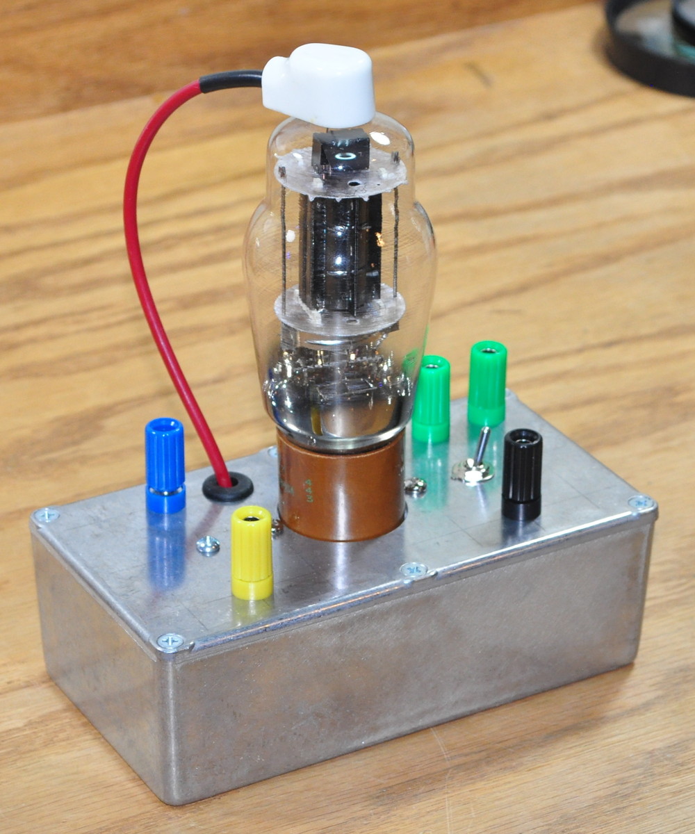
I say that it “used” to look like this because I’ve made some additions. The original jig was just to show what happens when the 800Ω cathode bias resistor is bypassed or not. It really wasn’t intended to do any performance investigations or even operating point checks. That situation needed to be changed.
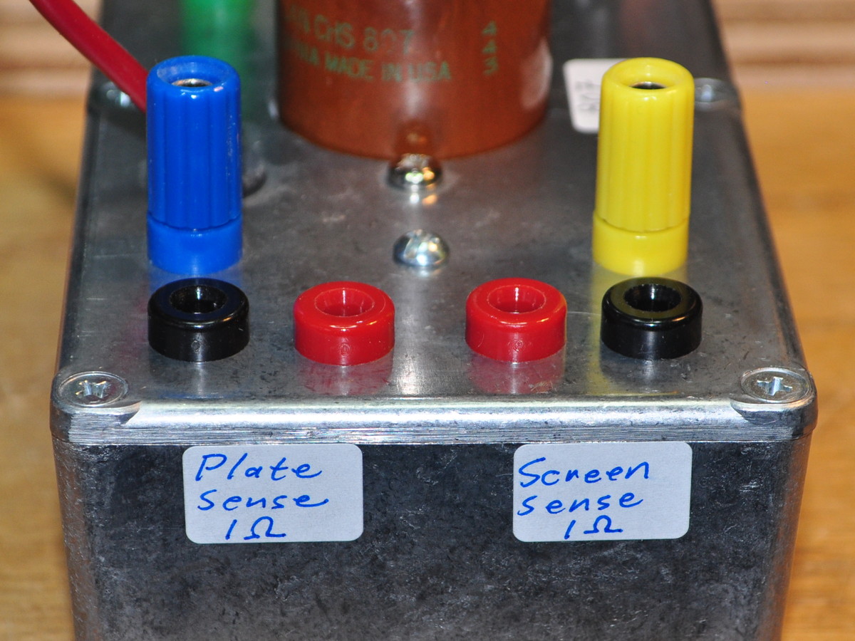
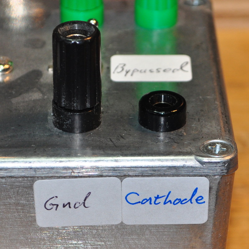
So I decided that I needed two things. First I needed some 1Ω resistors in series with both the plate and the screen. This will allow me to see exactly how much current is flowing in each electrode under various operating conditions. I also needed a test point for direct connection to the cathode. This way I can measure the voltages at each electrode so that I can calculate the screen and plate dissipations at various operating conditions. The top of the jig now looks like this.
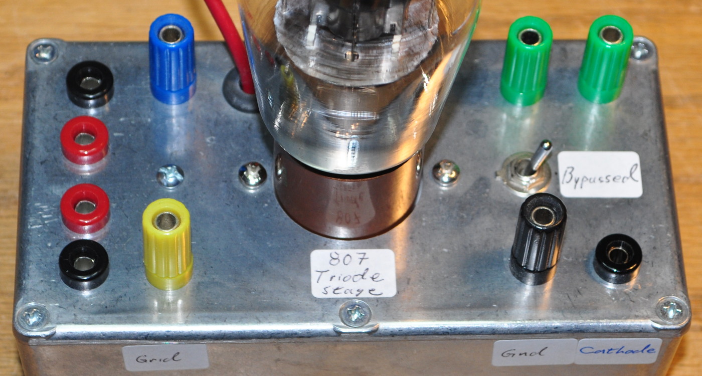
The banana jacks on the left are the sense test points and the one on the right is the cathode test point. Here is the resultant internal wiring.
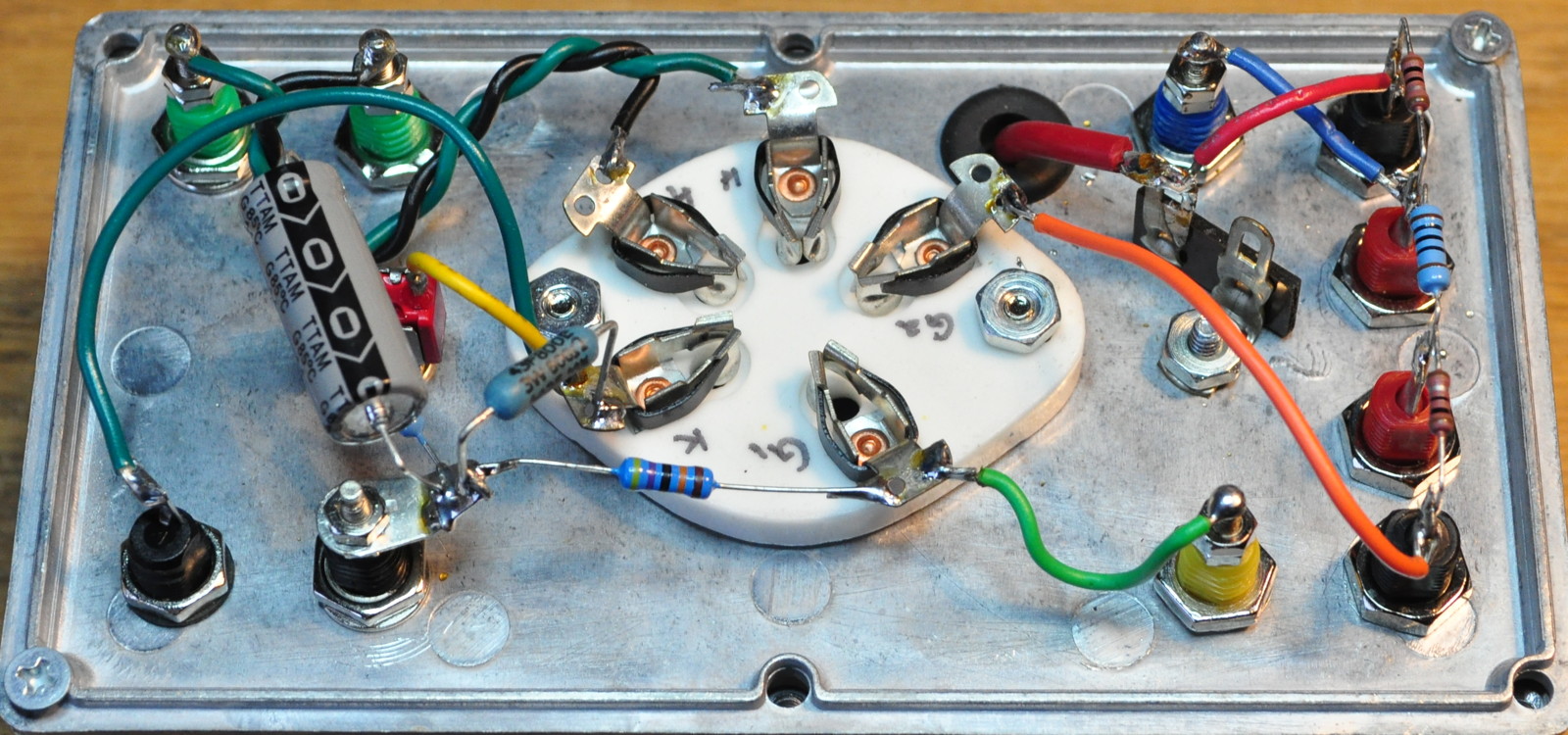
The dark green wire on the left is the new cathode test point and the resistors on the right are the 1Ω sense resistors and the 100Ω screen resistor as recommended by the data sheets for triode operation.
And just to make sure that I don’t get confused by the new added complexity, I included labeling for all my additions. See, you can teach an old dog new tricks.
Now I just need to get the stage hooked up to the prototype power supply and see how the tube looks around the Vp=400V plate voltage limit.
And Now, About That Testing
And I’m not talking about testing with the newly modified 807 jig. That will come in the next few days. Now I’m talking about some additional testing with the prototype power supply.
I got to thinking about the striking appearance of the 807 tubes and how they were going to look in the amplifier. I decided that I wanted to really lean into the ST shaped tubes. I looked around and decided to take a chance on a new production rectifier with the proper configuration; the TAD 5U4G Red Base Premium rectifier. Initially I had some reservations as it is labeled 5U4G and not 5U4GB. As such I wasn’t sure it could handle the higher voltages and currents this project required. But, in their advertising, TAD indicates that it is a suitable replacement for the 5U4GB. I decided to get one and try it out.
Here is how it looks compared to the 807 and the standard 5U4GB.
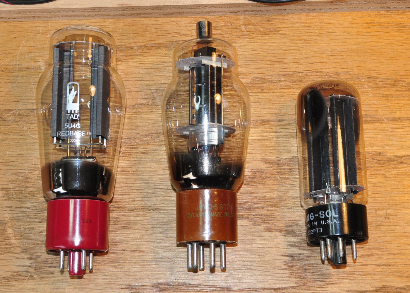
The 807 is in the center, the TAD 5U4G is on the left, and the 5U4GB is on the right. The rectifier is actually just slightly larger than a normal 807, and it dwarfs the standard 5U4GB.
So now that I had one in hand it was time to test the claim that it’s a suitable replacement for the 5U4GB. I decided to run it through the exact same conditions I did for the 5U4GB and GZ34 in the prototype power supply. Here is that data.
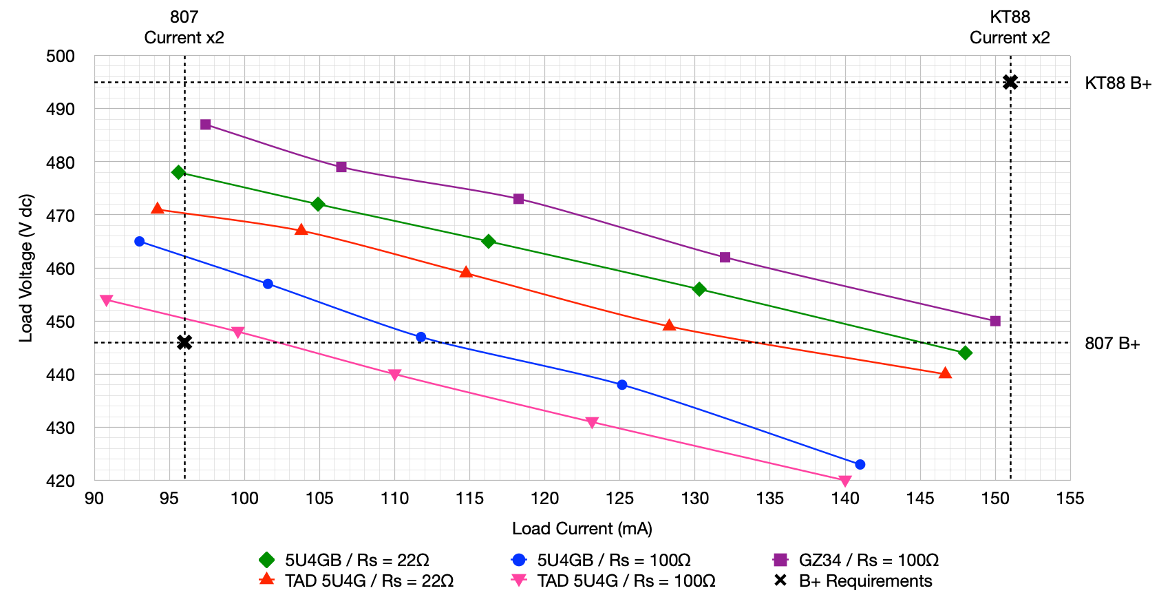
This is the same plot I include in the previous post with two additional data sets added. The redline is the TAD 5U4G response with the 22Ω protection resistors. The pink line is the same tube with 100Ω protection resistors. The voltage difference, at the 807 current requirement, with 22Ω resistors is just ≈8v (about 1.7% lower than the 5U4GB) and with 100Ω resistors is just ≈12v (about 2.6% lower than the 5U4GB). These responses are well within family for the 5U4GB. So it appears that the TAD 5U4G is in fact a 5U4GB rectifier in an over tall ST-16 envelope.
This makes for a very visually attractive tube which can be used in a lot of different amplifiers. Her’s how it looks under testing.
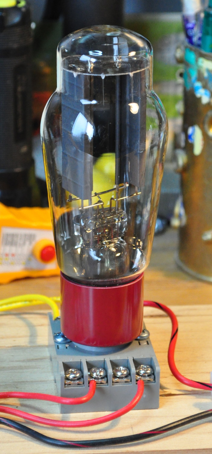
I’m glad I found this tube.
I’ll probably get to the 807 testing in the next week or so. I don’t intend to run the tube much over Vp=400V. I just want to make sue that it’s not as hard a limit as implied in the data sheets when run in a single ended purely class-A configuration.
As always, questions and comments are welcome.