
In my last post, I talked about the changes I’ve made to my 807 prototype jig so that I could investigate the 400v, triode strapped, plate voltage limit. Now I’ve managed to spend some time playing with the high voltage prototype power supply and my newly modified jig. As a result, I’ve learned a surprising amount about the 807 operating as a triode.
My work actually started with a comprehensive review of all the 807 data sheets and application notes upon which I could lay my hands. The first item of note is that few of the data sheets even mention triode strapped operation. And when they do, it’s in the role of an audio frequency amplifier and modulator, with two tubes in push pull configuration, biased for class AB1 operation. The sheets also all agree that, in this mode of operation, the maximum plate (and screen) voltage is 400V.
However, when reviewing the other listed configurations (classes AB1, AB2, B, & C in tetrode mode), one quickly sees that the maximum plate voltage can be as high as 750v with a screen voltage of 300V. Clearly the tube is designed to handle high voltage differentials between the plate/screen and cathode so the 400V triode strapped limit is not a physical constraint of the tube construction. This means that it must be an operational constraint. But the other operational constraints in triode mode are power dissipations, 25W for the plate and 3.5W for the screen (or 25W total; the data sheets disagree on this), and the maximum plate current, 120mA to 125mA dependent on configuration.
There is one more thing to consider in this discussion, and that is the way tube conditions change with signal input. In class-AB operation (as well as class B & C), the plate and screen power dissipations can grow significantly with signal input. Depending on the bias point these powers can almost double in some class-AB configurations. However, in single ended class-A operation, the maximum plate and screen dissipations will always occur with zero signal input. The quiescent condition is always the condition of maximum tube power dissipation. This provides important context.
In a triode strapped, push pull configuration, biased for class AB1 operation, it would be relatively easy to exceed plate and screen dissipations with large signal inputs. I happen to know (from my investigations) that with 400V on the plate and an idle current of only about 45mA, the plate dissipation is already close to 18W. Slipping from class-A to class-B as the input signal increases could easily exceed the 25W maximum plate dissipation limit. Increasing the plate voltage would make this condition much worse.
Since I already decided that the tube could handle plate voltages much larger than 400V, and knowing that the idle condition is worst case for electrode dissipations, I surmised the real constraints for single ended class-A operation are the maximum plate and screen power dissipations and the maximum DC plate current. So I shaped my investigations to track the electrode power dissipations as I increased the B+ voltage. This should quickly show if there are any limitations I haven’t considered.
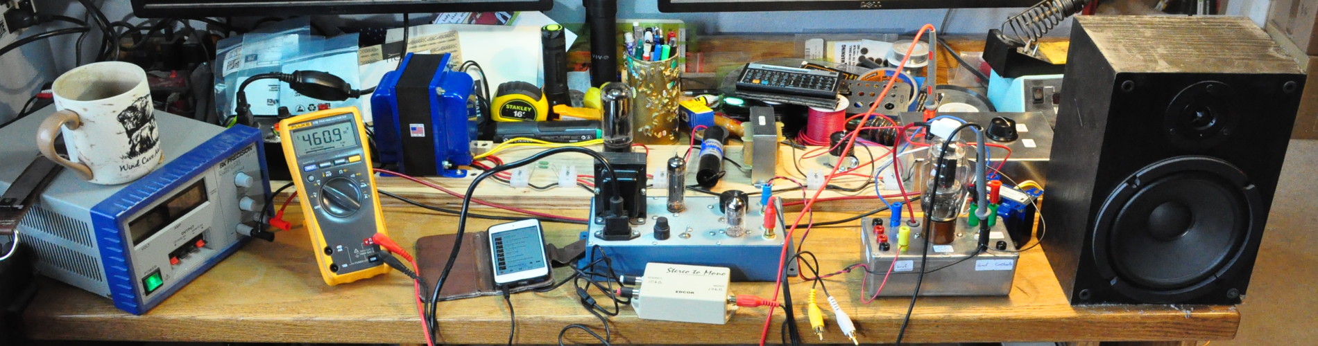
With the newly modified 807 prototype jig and the prototype power supply, it was a simple matter to configure a test setup to take some measurements. Here is the basic setup on my work desk.
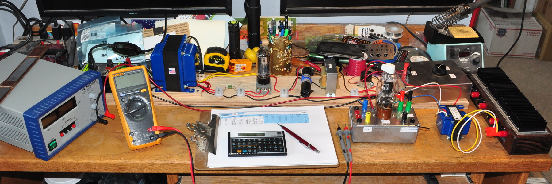
The prototype power supply is along the back, my low voltage bench supply on the left powers the 807 filament, and I’ve loaded the jig with an Edcor GXSE10-5K transformer and an appropriate dummy speaker load. Even though I was not planning on pushing a signal through the setup, I wanted the actual plate load on the test rig as I took data. The single rheostat load box behind the output transformer provides a series load on the B+ line to adjust the B+ voltage. With a simple adjustment I can change the B+ by a reasonable amount.
My methodology was fairly simple, I would set the B+ voltage, check the electrode voltages and currents, calculate the power dissipations, look for any anomalous behavior and then increase the B+ again. I started just below the initial design point (Vp=399v) and then increased the B+ in roughly 5V increments. Here are the measured voltages and current plotted as a function of B+ voltage.
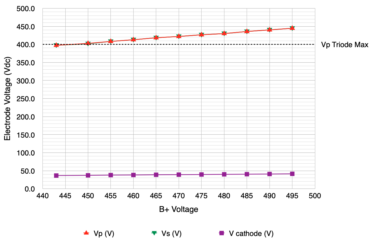
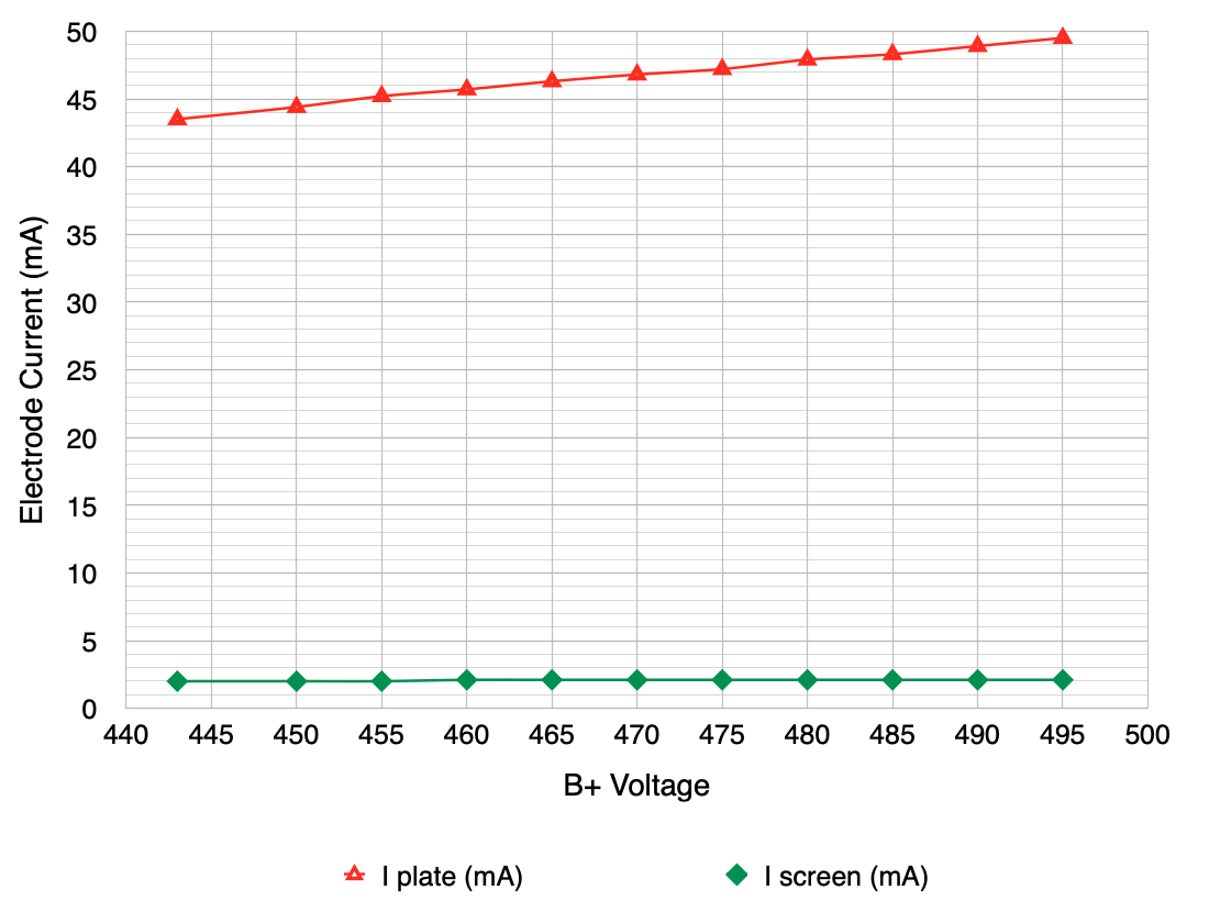
For all but my initial data point, the plate voltages all exceeded the published 400V maximum. However, the current levels all stayed very reasonable and there was no apparent non-linear behavior in the response. And here are the power dissipations also plotted as a function of B+ voltages.
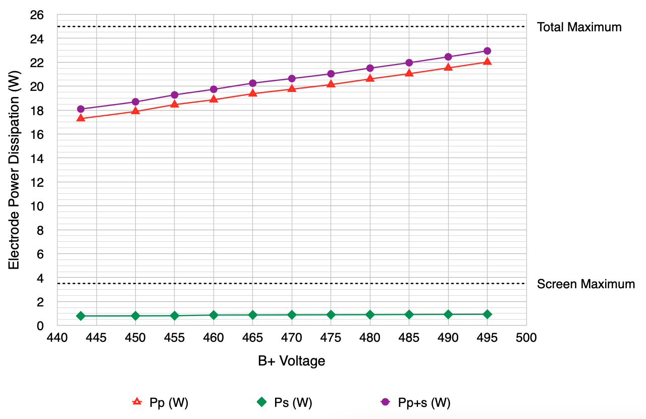
This was the result I was expecting (and for which I was hoping). Even as the plate voltage exceeded the published maximum by almost 12% (44.7v) the plate and screen power dissipations stayed well with the published maximums. This is a great result and shows that the hard limit published in the data sheets is not applicable in my configuration. I will be able to run the stage as designed and not have to back off on the B+ voltage at all. Or worry about slight B+ over voltage conditions from changing rectifiers.
This result allows me to proceed on the detailed design but it was not the end of my investigations. I mentioned above that the 807 (and 1625) data sheets didn’t always address triode strapped operation and when they did it was only in one configuration. There is one exception to this statement. There is a rather voluminous 807 application report published by Standard Telephones and Cables Ply. Limited of Sydney, Australia, from June of 1954. This report contains much more information of the usage of the 807 tube including triode strapped operation. In total it is 43 pages long.
In this report, under the ratings section was this curious note about triode strapped operation.
In order to avoid parasitic oscillation the plate and pin 2 should be connected together through a 100 ohm resistance or an RF choke of 20 microhenries.
I did not find any mention of this on any other 807 data sheet or application note. When I originally built my test jig in 2017, I included a 100Ω resistor between the screen and plate just out of caution. Here is that resistor in the original jig wiring.
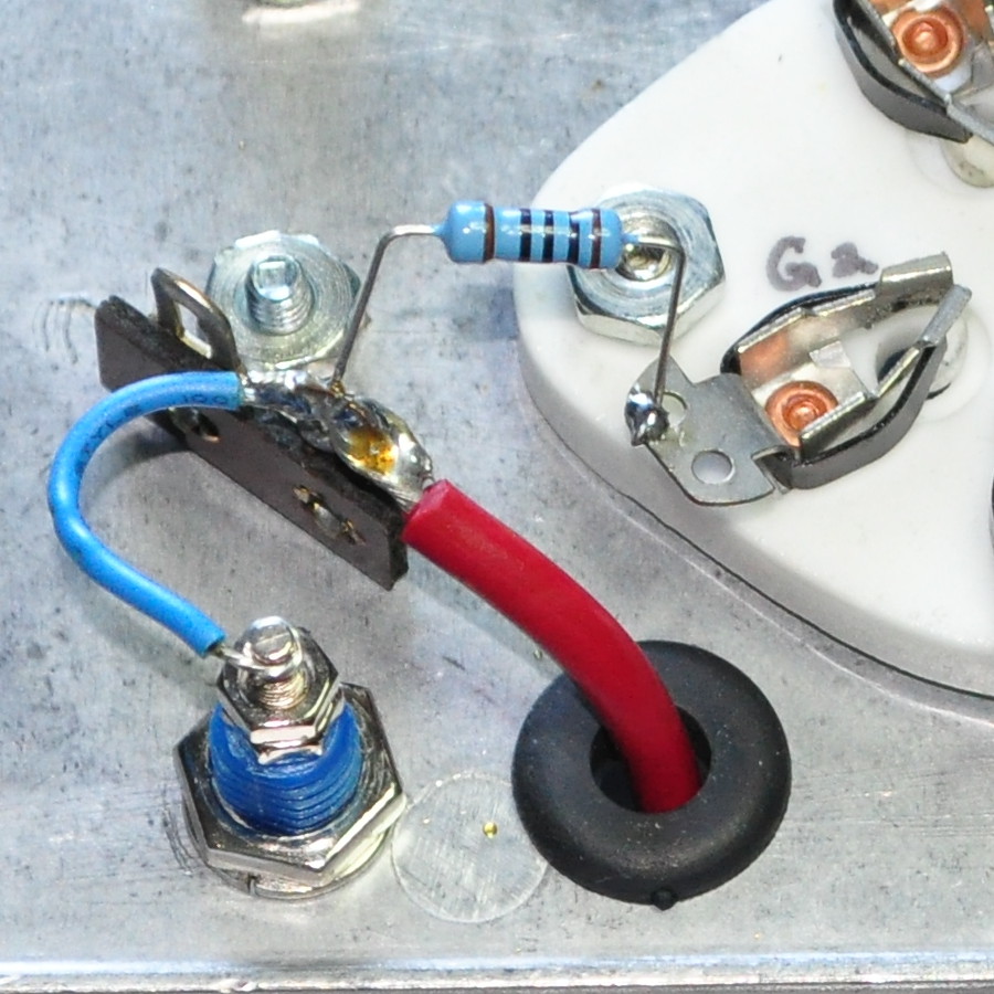
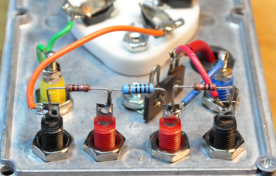
The resistor is connected directly to the screen pin socket. The red wire in the picture above is the plate lead which attaches to the top cap of the 807. When I modified the jig to include sense resistors, I retained the 100Ω resistor. Here is the wiring in the modified jig.
So I first performed my elevated B+ voltage investigation with this configuration.
Then I got stupid.
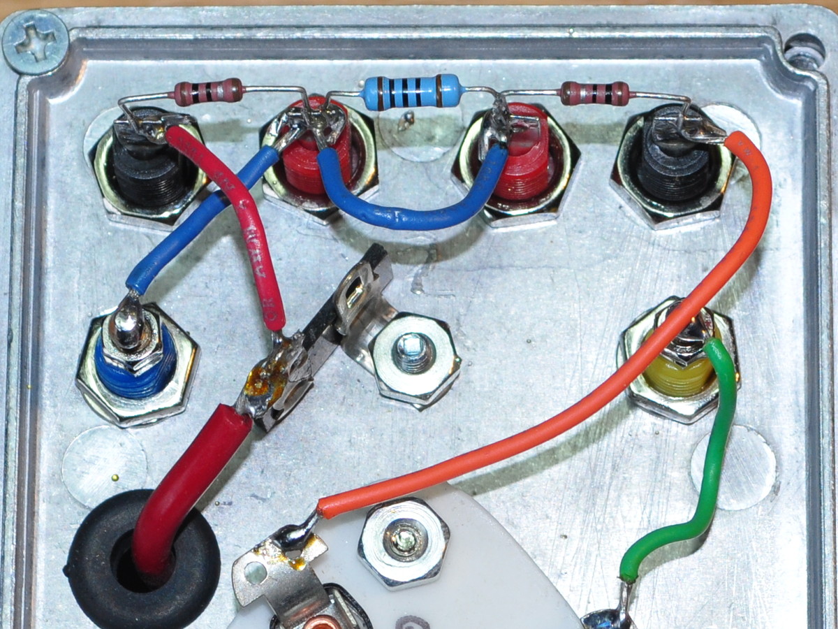
I began to think that, because I had only found this one foot note in one application sheet, maybe it wasn’t really required. I convinced myself that maybe it was included, like the 400V triode strapped plate voltage limit, due to some other design reason associated with class-AB1 operation. Maybe it didn’t really apply to my case. After all, the note was not included in ANY other data sheet or report. So I again modified my jig, by jumpering the little 100Ω resistor like this.
I reasoned that this should tell me immediately if this was really required or just a nice to have. So I wired the jig back into my test setup and started to duplicate my measurements. I immediately noticed that the electrode voltages were all different. The plate and screen currents seemed close but even the B+ seemed a lot higher. I should note that I was still using just my Fluke 179 multimeter to take measurements. I simply could not duplicate the measurements I’d already taken, and even the measurements I did take did not seem self consistent.
To further try and figure out what was happening I grabbed my oscilloscope and started to check some waveforms. All I could find was oscillations! The plate circuit was oscillating in the one to five MHz range, jumping all over. If I even slightly change loading, things would change again. So I lowered the B+ voltage trying to get operation to settle down, and that ADDED an AF oscillation on top of the RF oscillations. I could not make the circuit stable at all.
Again I opened up my test jig and cut the jumper off the 100Ω resistor. And again I wired the jig back into my test setup and started to duplicate my measurements. And just like magic, I verified every one of my earlier test points and the oscilloscope showed no signs of oscillation. Evidently that 100Ω resistor is REALLY required.
Once I got my power stage working again I decided to do one more thing which I hadn’t done before. I removed the dummy speaker load and replaced it with a speaker. Then I configured the 4S preamp with a 12AX7 as a surrogate driver and attached an iPod. Here’s my final test assembly.
Once into this configuration, I played music through the power stage at B+ voltages from 445v up to about 470v. I was looking for anything which would suggest oscillation or “off” performance (e.g. sibilance, hissing, buzzing, etc.). I didn’t detect anything wrong. In fact, considering that it was just a thrown together prototype, it sounded remarkably good. With a properly designed and optimized design, this amp should sound very nice.
Now I just need to get the electrical design completed and get to work on the chassis. Luckily, the weather here has clearly shifted towards spring so my shop is warming up nicely. I should be able to get some time between other spring chores to get some work done on the chassis design and build.
As always, questions and comments are welcome.
Matt, did you get the STC 807 report? It is the 807 bible. If you didn’t, you can find it at Blueglow Electronics sketches page. Here is a link to the download on his page.
https://blueglowelectronics.wordpress.com/wp-content/uploads/2018/02/807stc.pdf
I don’t know of any better information than that.
sorry, I just read that you do have this report.
No worries. 🙂