
Well, my blog seems to be quickly becoming a list of things to avoid doing. I’ll get back to the more technical stuff soon but in the mean time I have one more blooper to share. I hope there aren’t too many objections.
So I have a new amplifier I just finished which will soon be added to the ever growing list of amplifiers on the web page. But when I was putting it together I managed to destroy a couple of expensive tubes due to a very simple error early on in the design process. Let me explain.
When I start to lay out an amplifier’s internals for point-to-point wiring, I tend to do some planning about where everything is going to go. I don’t always follow it exactly, but it does allow me to virtually prototype my layouts to see if there are crowded sections, or places where distances are too great for a component to bridge. I then use the layout diagram to check things while putting the amp together. And this amplifier was no exception.
When I do this, I make a layout drawing of the underside of the top plate, label all the tube connections, and insert components on the drawing. Here is a small section of the one I made for this amp.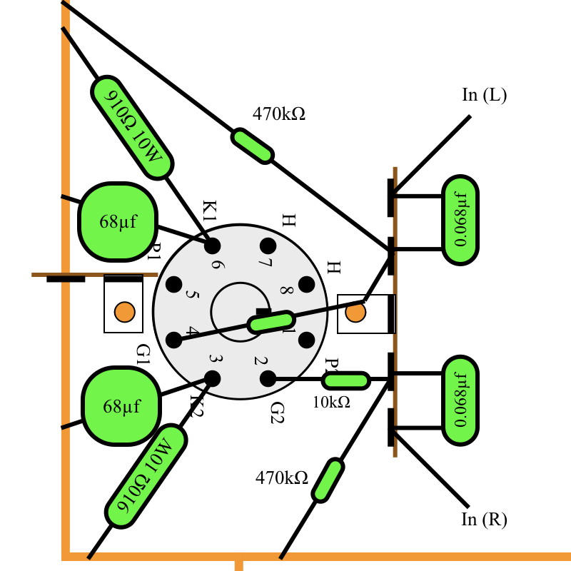
This is the wiring diagram for the large dual triode power stage in the amp. This way I can see where all the components go and where connections are to be made.
So I assembled the amp, checked (and then re-checked) all the connections to be sure they were correct, and performed my initial power on checks. The entire signal/drive stage checked out fine, as did the left power channel. However, the right power channel gave improper voltages and very high plate currents. I then shut off the amp and checked everything again. Again I found no mistakes.
I then made the assumption that, of course, I had gotten a bad tube. These were used tubes and it was very conceivable that I had one with a bad channel. So I replaced the tube with a new one and tried again. And again, bad voltages and high currents were seen in the right power channel. It is possible I got two bad tubes but not very probable. So I began checking my circuit again. This time in great detail and verifying assumptions as I went.
Just by chance, when I started to review the internal layout, I picked up the front page of the power tube data sheet and looked at the pin basing diagram. And that’s when I saw it. The labels on the basing diagram did not match the labels on the layout drawing above. The labels on pins 1 and 2 were reversed from what I had assumed. Here is a picture of the improperly assembled wiring.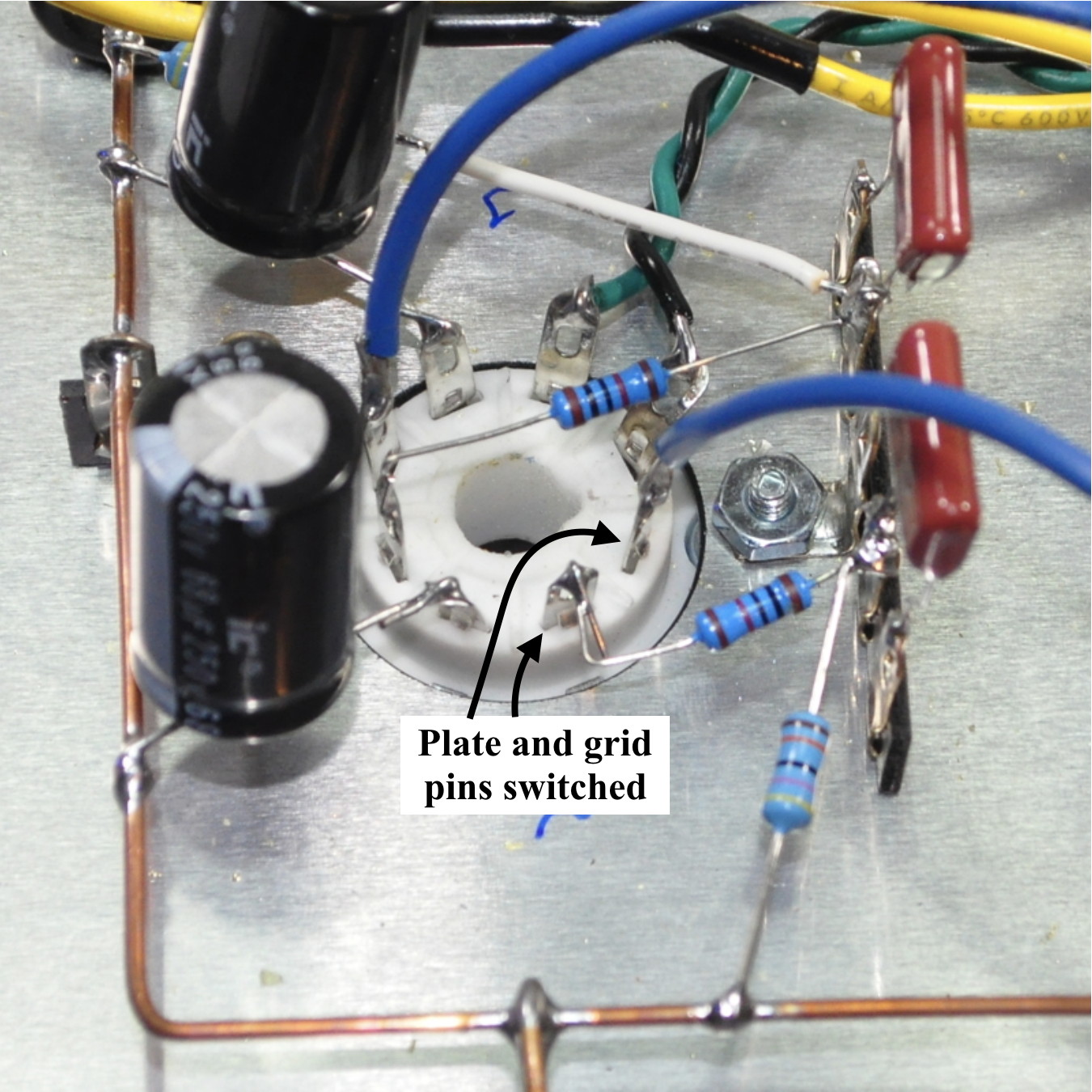 You can imagine the result. With the plate at essentially zero potential and the grid at a very high positive potential, I had instantly fried that same triode in both tubes. I went back and swapped these two wires (and inserted another big dual triode) and the amp worked perfectly.
So the simple moral to this post is, again, always check your work. Just because you took notes and documented everything, doesn’t necessarily mean that those notes are correct. This is just as true for a thirty year Engineer like myself as it is for someone just starting out. And this mistake cost me about $50 USD in tubes. An expensive, but well learned lesson. I think I’ll be inserting an assumption check into my design process in the future.
Thoughts?
Pingback: Fixing a Mistake | Cascade Tubes
Matt, this looks as though it might help me in figuring out the connections for the 12au7/6as7 you designed. I have been drawing it out freehand to help me avoid making mistakes when I come to putting it together but your approach makes it very clear. Can you advise which drawing program you used for this if available. Thanks.
John; This particular drawing was just done in the Apple “Keynote” presentation application. But I’ve also done similar layouts in PowerPoint and SketchUp. Once you get some basic building blocks made it goes pretty quickly. Hope this helps.
Hi Matt,
You taught me everything I know about building tube amps except the few little tricks I came up with myself: As you saw on my guitar amp (after I wired the 6DJ8’s on the headphone amp while looking at a 12AX7 pinout), I now use a sharpy and write directly on the underside of the aluminum plate; voltages, grounding, pinouts, etc…
I think I’m going to start doing this. It’s a simple and effective solution.
Don’t be so hard on yourself, stuff happens.
40+ year engineer here, and I still blow stuff up occasionaly, but I do it in a sometimes spectacular manner, I usually use a 480V industrial power feeder to do it – definitely wakes you up. (240 volt servo amplifiers seem to dislike being connected to 480 volt power)