
So last night I posted about a mistake I made in wiring the latest project. And because of when and where I made that mistake, it took all afternoon to correct it.
The mistake I made was that when wiring the tube filament circuits, I wired the 12AU7 sockets for 12.6V instead of the 6.3V, which my project uses. Then I proceeded to do all the signal wiring on the two 12AU7 sockets before I caught my blunder. This is not the first time I made a mistake like this and I’m sure it won’t be the last. However, it can be a little frustrating all the same.
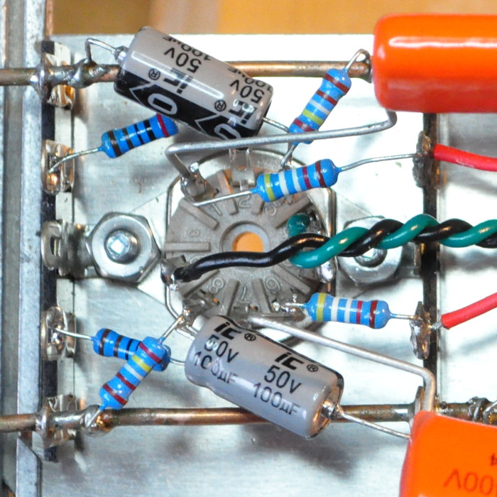
In my last post I included this picture:
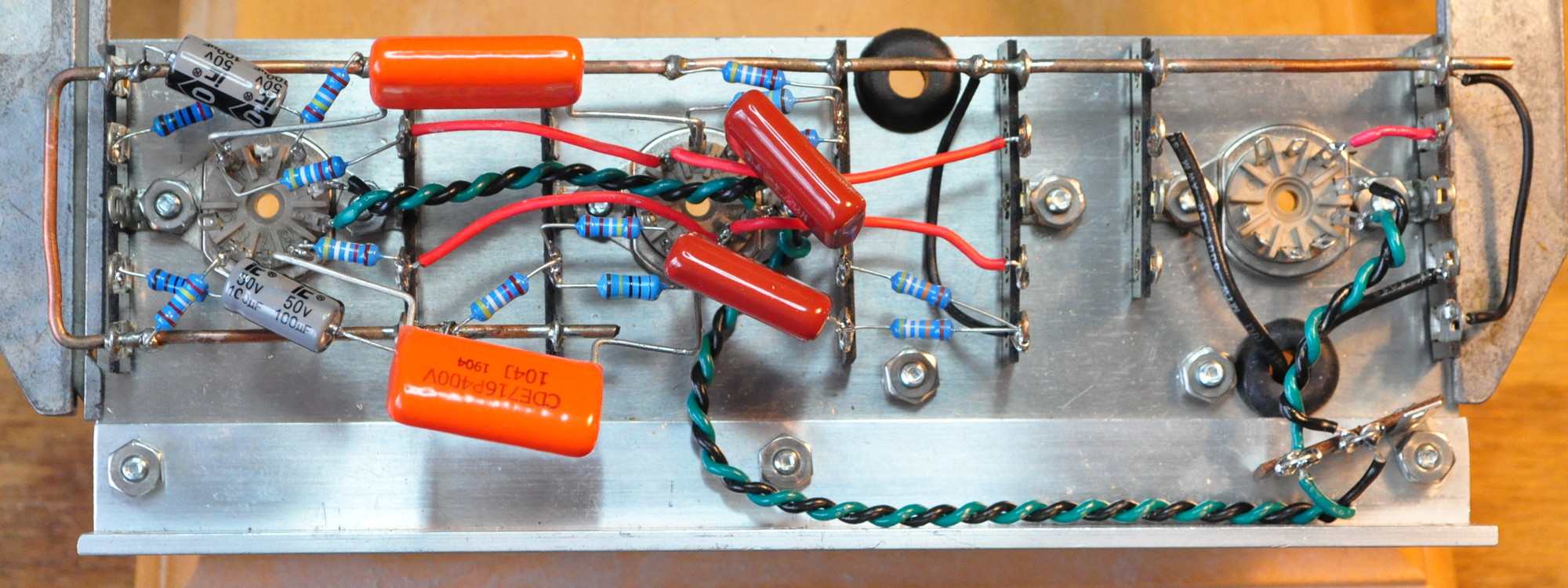
Here, if you look closely, you can see that the filaments are wired to pins 4 and 5 on each 12AU7 socket. They should have been wired between pins 4-5 and pin 9. What’s more, with the two output capacitors and all the resistors where they are, I was afraid that I was going to have to remove a substantial number of components to get access to the filament wiring. I went to bed last night with this little problem rattling around in my brain.
As is normally the case in such matters, a good night’s sleep and my morning coffee provided some welcome calm and perspective. So I took a long look at the assembly to see exactly how much work might be involved. I soon realized that the situation was not nearly as complicated as I had originally anticipated.
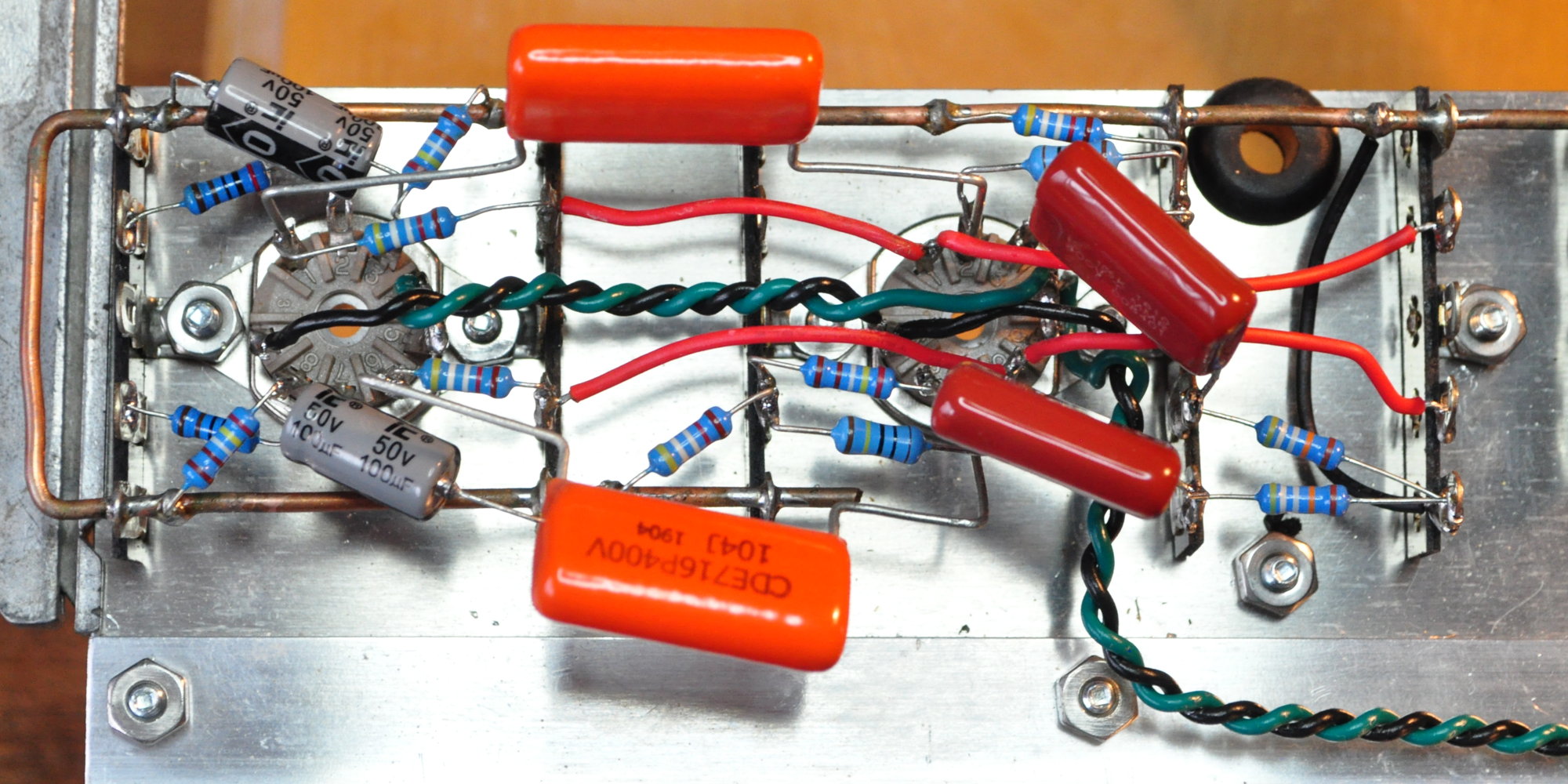
Here is a picture of the first step in my repair process:
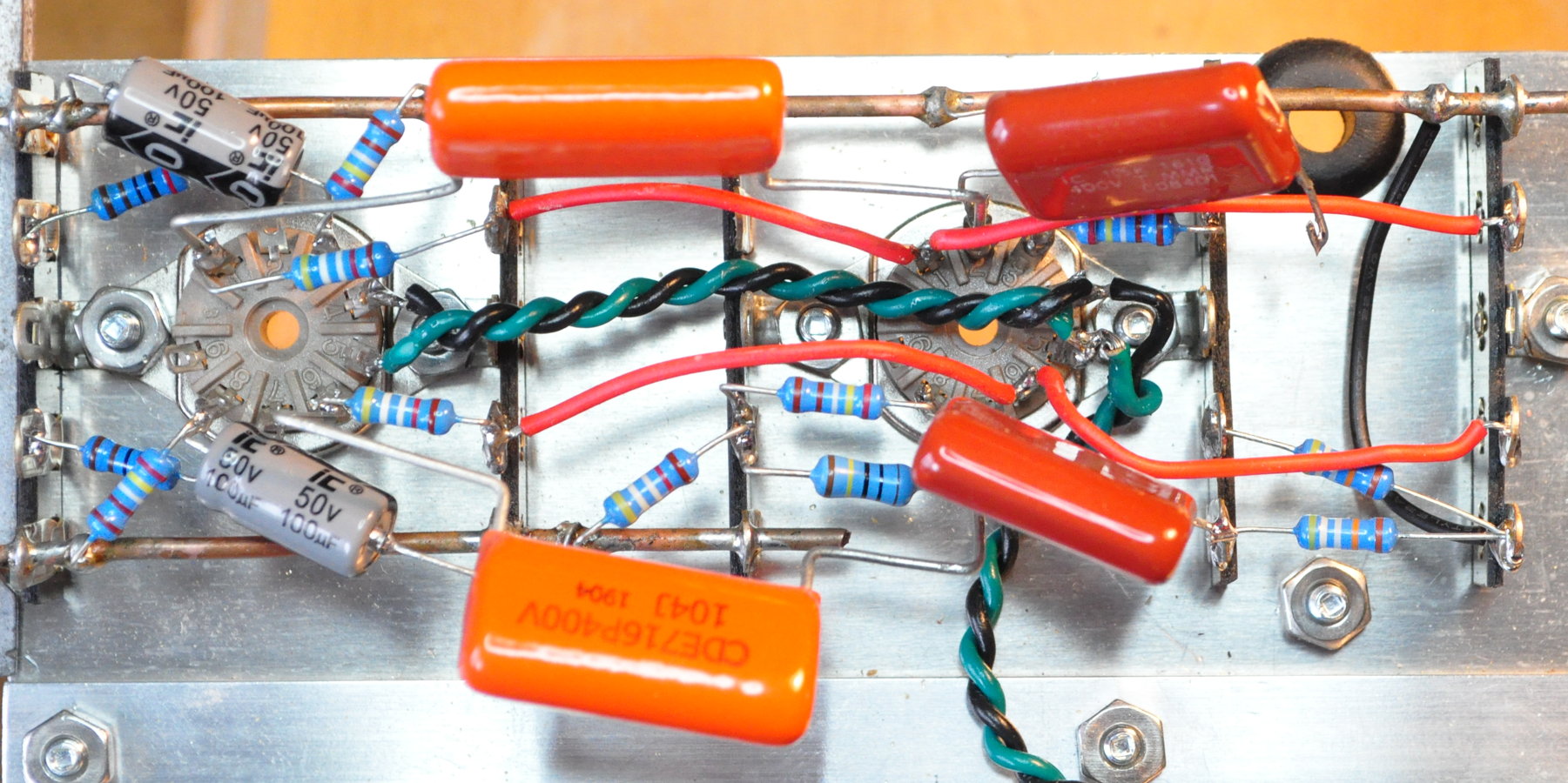
In this picture I have simply unsoldered one leg of one of the output coupling capacitors and moved it to the side. I have also moved the two B+ feed wired from the right hand terminal strip. From this picture it is seen that by simply moving a single component I obtained much improved access to the filament wiring. It is still a difficult access, however being open from the top does mean that I have relatively unfettered access for a soldering iron.
The next step was to remove the incorrect wiring. I could have tried to make use of the wire that was there, but this would likely have proved problematic for a number of reasons. I decided it was a better idea to sacrifice a few inches of twisted pair and use a new section to do the rewiring.
The picture below shows the wiring cut out to give access to the tube sockets.
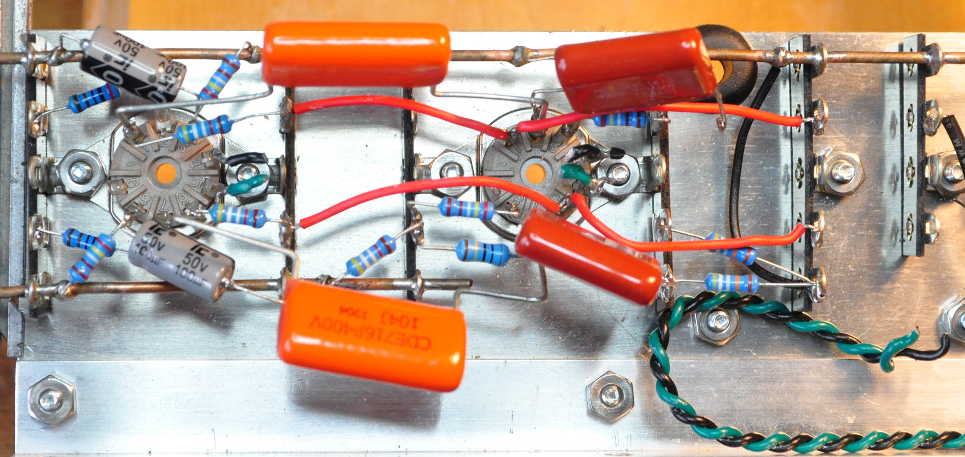
I determined that the wire from the terminal strip on the right was of sufficient length already. As such, I just snipped it off and moved it out of the way. The wiring between the two 12AU7 sockets was simply cut out. Now I was in a position to clean up the sockets and move forward.
I first removed the stubs of wire from the socket terminals and cleaned up everything making sure there was no stray solder or wire pieces. Then it was a simple matter to wire in the central socket with an addition piece of twist lead to feed the left most socket.
Here is the new filament wiring on the central socket:
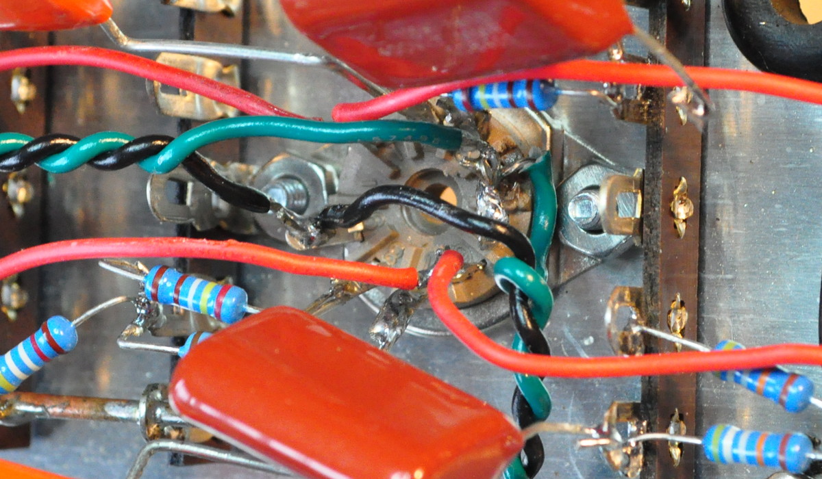
Here can be seen the green wire bridging pins 4 and 5 and the black wire connected to pin 9 (i.e. the filament center tap). The twisted pair for the other tube has also been soldered in at the same time. Here is the left most socket wiring:
This was the simple one.
At this point, all that was left to do was move the wires and components back into the right spots and resolder the one output coupling capacitor lead. With everything done and back in place, the assembly looks like this:
I was very relieved to get back to this point. Before I do any more, I think I’m going to perform a little checkout of this assembly and make sure filaments are operational and the DC voltages are all correct. Once that’s done I’ll get back to finishing the power supply and filter components around the 6AC4 socket on the right.
When I discovered this problem last night I was kicking myself for making such a wiring mistake. I was sure I was going to have to tear everything apart and start over. But a little distance from the problem, some time to contemplate, and some more calm nerves helped me focus on a much simpler solution. This is another good lesson for me to remember in the future. Because the one thing of which I am absolutely sure, is that this is not the last mistake like this I’ll ever make.
As always, questions and comments are welcome.
Excellent recovery Matt. I’ll take on board that process next time I do something similar. The heater wiring still looks neat.
I cringed when I saw the IC 100uf/50V electrolytic caps in your photos. I won’t use ICs in any of my builds anymore. In my experience they fail prematurely and leak something awful.
The last time I had a capacitor leak it was on the original 6V6 Lacewood configuration. It was an axial 47µf 350V filter cap but I can’t identify the brand. I discovered that about 8 years ago. I routinely open up projects just to see how things are doing and I haven’t found a leaky capacitor in years.
I do however routinely use IC caps. I’ll keep my eyes open for problems.
However, now that I look at those bypass caps on this project, they have the old style IC polarity markings. These were the same markings on the leaky capacitor in the lacewood from years ago. Although I didn’t have any pictures of the manufacturer logo from that capacitor.