
Ever since I completed the Optimization of the 6V6 SE-UL I have been saying that I was going to do the SE-UL optimization process for more tubes. So yesterday I finally started to make plans.
After looking at what I had done before, I decided I needed a better setup. When I did the 6V6 study I just wired up a circuit on my prototyping station. It was not particularly easy to work with and It was a little unnerving probing around all that high voltage taking hundreds of measurements. So instead, yesterday I put this little test jig together.
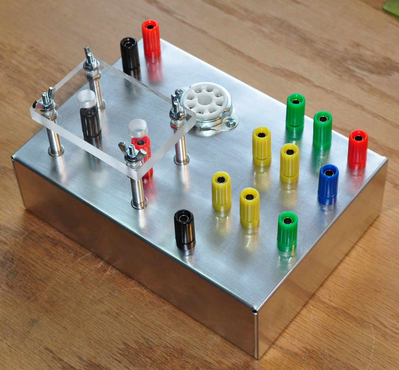
This jig has several improvements over the last approach. First, this jig uses lots of binding posts / banana plug jacks. This makes wiring up the circuit and providing power easier and safer. Second, there are some features included so I don’t have to worry about them. This jig is wired to support the standard power pentode pinout used by all the major power tubes (6V6, 6L6, 6F6, 6W6, KT66, KT88, etc.). There is also already a 470kΩ grid resistor in the box as well as a 1kΩ grid stopper. I thought the grid stopper might be required due to all the stray capacitance in the jig. There are also precision sense resistors in the box so I can easily monitor plate and screen currents. The shield is there because this was the only place I would likely mount components between posts. The shield is removable and provides an added level of safety. The whole thing is built on a little Bud AC-402 aluminum enclosure. I have a whole stack of these little boxes sitting in my stash for building projects such as this.
Starting on the upper left, the red and black posts are the input to the tube. I’ll probably drive this with the 4S preamp to give acceptable drive levels. Next is the tube socket which is ceramic to handle the heat of the larger tubes. The two green posts on the upper right are for the filament voltage (pins 2 & 7). The red post is just a B+ binding post for the output transformer. It doesn’t connect to anything underneath. The blue and green post on the right are for the plate and screen connections respectively. The pairs of yellow posts directly to their left are for 1Ω precision sense resistors in line between the tube and binding posts. A quick voltage check there will tell me the exact plate and screen currents. The black post at the bottom is for the power stage ground connection. All the black binding posts are tied together and tied to the aluminum chassis.
This brings us to the red and black posts under the shield. This is for the cathode load. Normally there will be a cathode bypass capacitor mounted between these and there will be connections to a cathode bias resistor (fixed or variable). There are holes in the shield for taking measurements or plugging in banana plugs. The shield should keep test probes from inadvertently contacting exposed component leads or shorting anything to the grounded enclosure.
So that’s it. One simple test jig all wired up and ready to go. Now I need to make time to start taking measurements. I think my first set of measurements will be with a 6L6 and a 5kΩ plate load. It should be interesting.
Pingback: Everyone Make Mistakes | Cascade Tubes
Pingback: More on Tube Testing | Cascade Tubes
Well, the optimization is complete. The page is located here: https://www.cascadetubes.com/optimization-of-the-6l6-se-ul/
Quite a bit different than the 6V6 effort.
The results should be useful for future amp projects. Thanks in advance for going to this effort.