
I’ve been working on the color preamp over the last few days as I’ve had time. My volume control and output capacitors are supposed to arrive today so it shouldn’t take too much longer to finish it up. However working inside the small chassis is a challenge.
I’ve got the entire power supply wired up with the exception of a dropping resistor. Here’s how it looks so far.
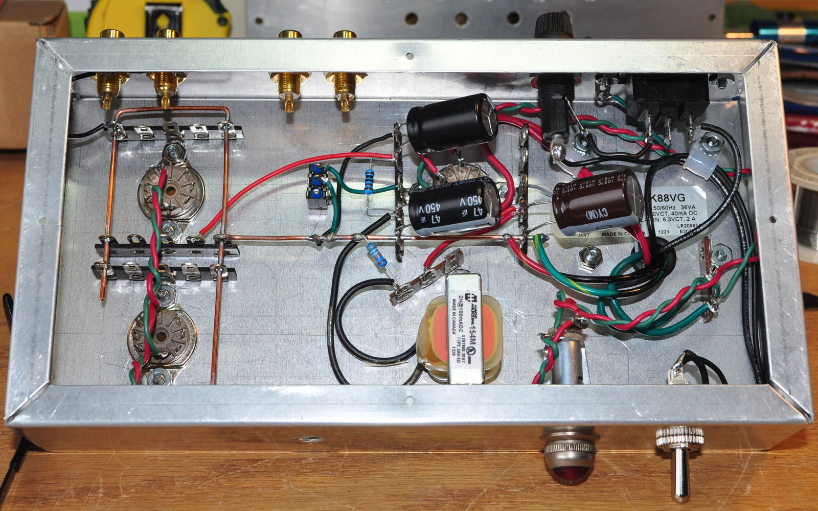
The power supply uses a 33µf first capacitor followed by an 2H/47µf LC filter stage followed by a 1kΩ/47µf RC filter stage. The power supply should have about 20dB of margin over my desired -90dB ripple level. However the voltage will likely be a little high. I was targeting a B+ of about 300V but I’ll have to see what dropping resistors I have available. The 6CA4 drop is only about 10V at the low current levels. A 1kΩ resistor drops ≈13v at this current level. My power supply calculations show about 316V with no dropping resistor so I may just use another 1kΩ before the choke to get me close to the 300V B+ I want.
I also had to turn the choke around to make room for a convenient location to mount the dropping resistor. This also gave me a nice spot to mount the 499kΩ PS bleeder resistor. With the power supply essentially complete, I can now start focusing on the audio side of the circuit. I get the feeling that things may get a little cramped before I’m done.
As always, questions and comments are welcome.
Grounding point
In you grounding philosophy blog entry you mention among other things…Power amp signal and chassis grounds shall be tied together at only one point, this point shall be within the chassis, and this connection shall have a DC impedance not to exceed 2mΩ….
For this amp where would you plan to locate this connection?
The hard fixed connection only applies to power amps. In my systems, my main earth ground connection is usually within the power amp. As this is not a power amp but rather a preamp, the fixed single point ground connection does not apply. This unit gets a ground lift connection between the signal and chassis grounds. This is implemented as in the following illustration.
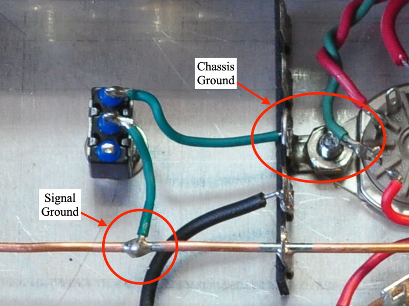
This allows me to configure the earth grounds according to system configuration and power system noise level.
Does this make sense?
I think I’ve got it. if connected to the power amp the chassis ground connection is opened and only the signal ground is active.
Almost. The preamp still has the safety ground due to the three wire mains connection. This provides the appropriate safety coverage. But the preamp signal ground is referenced to the power amp via the interconnect cables. And the preamp signal ground is referenced to the mains safety ground through the power amp. But there are no ground loops due to a redundant connection to the mains safety ground.
That chassis is very clean and spacious as compared to MANY hand wired radios and TV sets from days gone by. In many of the old sets there were multiple layers of components “scramble wired” in true point to point fashion. Almost impossible to trace anything out. You are doing great!
It looks like I’ve arrived at the “multiple layers” point 🙂
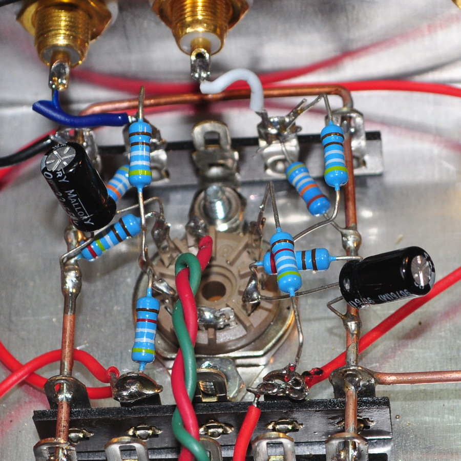
Working inside this little box is really a challenge.
Looks like that socket is fully wired, so not too bad.