
I’ve been making an effort this morning to get my head around the internal layout of the 6L6 SE-UL amplifier. Unfortunately, I keep being stymied by the sheer physical size of many of the components.
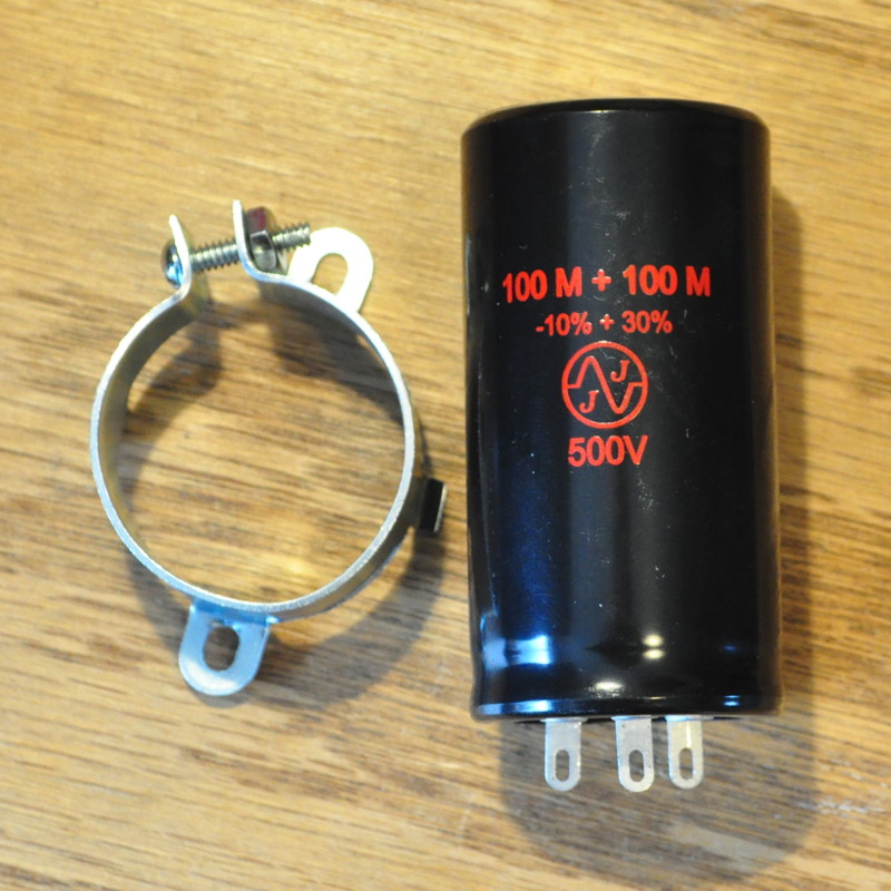
This all starts with the fact that, even though the power stage design is driven by the results of the 6L6 SE-UL optimization study, I am sizing the amp to be able to take the KT88/6550 power tubes with no modifications. I also am cognizant of the startup transient conditions which may let the B+ voltage level climb above steady state level by as much as 50v. So I decided that I needed electrolytic filter capacitors rated at 500V. I settled on ANH series capacitors made by JJ Electronics. This is where my problems started.
There are five of these filter capacitors in the amp; two 30µf and three 100µf. Each one is an axial leaded cylindrical package 1″ (25.4mm) in diameter and about 1.65″ (42mm) in length. When I put these into my layout drawing, they simply looked comically large in relation to everything else. Here’s the partial layout from this morning’s work.
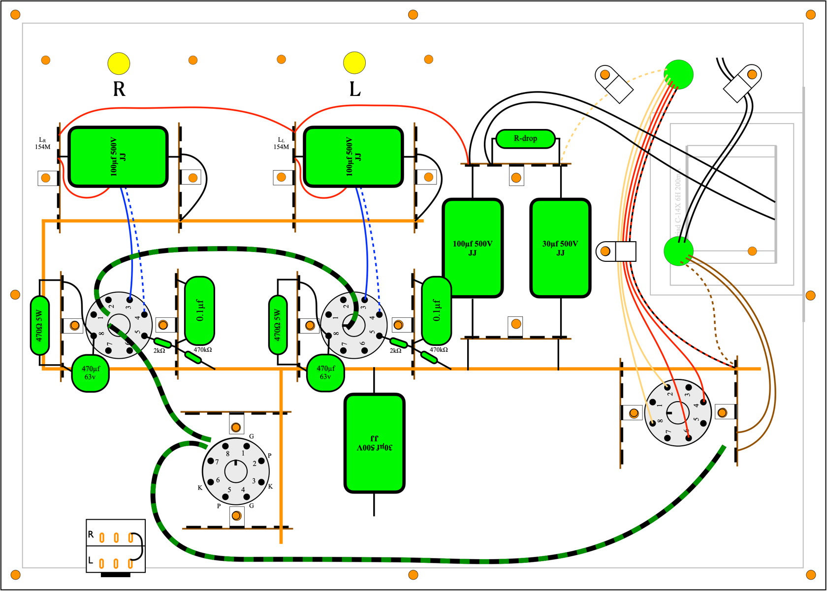
The big green rectangles are the filter capacitors. The top plate upon which everything is laid out is 14″ x 10″ (356mm x 254mm). Then I added the main filter choke, a Triad C-14X 6H open frame model, and it ate up a bunch of space. Even the coupling capacitors, CDE 716 Series 0.1µf 600v, are larger that I expected.
So now I’m to the point that every time I look at the layout drawing EVERYTHING looks comically large. I know this isn’t really the case. And I know that in the end everything will fit with space to spare. I just have to keep reminding myself that these layout drawings always look more crowded than the actual amps. If for no other reason than the two dimensional nature of the drawings.
Well, back to work.
As always, questions and comments are more than welcome.
Have you ever considered top mounted caps?
I’m considering a top mounted. 100uF/500V “snap in” for a current project. One reason, aside from making room under the chassis, is to give a little visual interest to an otherwise sparse top.
Yes I did as a mater of fact. I have a couple of these in my capacitor stash and I considered using them in this amp.
I used these on the Lacewood amps, and on the First Amp, the Recovery Amp, and the Rebuild Amp. However, as I was working the top layout for this amp, I was concerned about first how the amp would look with the big KT88s in the power tube slots. I wanted something mostly uncluttered to showcase the big tubes.
Second, I was concerned about the overall size of the top plate. The amp with the largest footprint that I’ve built so far is the Lacewood with its 14″ x 11″ top plate. Even though I routinely tell people to go with as big a chassis as possible, the Lacewood has taught me that if the chassis is too big, locating the amp in a typical home can become problematic. The depth in particular can become a problem on typical shelves and side tables. This is why I shaved an inch off the depth dimension on this amp verses the Lacewood. I wanted the extra room front to back for ease of installation.
Is the input going to come in from the back and run along the side to the potentiometer the same way the Marblewood does?
That’s the plan. There are a couple of Hammond 154M 2H chokes on that wall next to the output transformers but they are tiny. I’ll have no problems getting the two input twisted pairs by them.
Thanks for the details. Is the power switch going to be on the other side of the front panel like the Marblewood too?
This amp is going to be externally pretty similar to the Marblewood; just larger. The power switch and pilot light on the front left and the volume control on the front right. The same similarity on the back as well. Anytime using the “power supply on one side and the amp on the other” type of layout, this control layout just makes sense.
I’m still waiting to hear about the power transformer from Edcor. The few other components I needed should be here this week. I need to get to wok on that spalted alder.
Not much you can do about the size of the caps. The layout looks logical. Probably will need some tweaking.
Questions – Will the filter choke interfere with the primary and heater leads coming out of the power transformer? Looks kind of tight in that area.
Can the size of the chassis be increased if needed? In my career, I was usually told no, it’s got to fit in the space we allotted you🙀
The primary filter choke sits below the plate by about 3/4″ so there should be lot of clearance for the transformer wires. I could increase the size of the chassis but right now I would like to hold the size where it is.