
Today I took some time to install the signal ground bus and wire the transformers. But I also wanted to discuss a specific aspect of transformer wiring for the B+. I often get questions on this topic from people looking at the 6336 SET Amplifier. Let’s take a look.
But first, here’s how the underside of the 6L6 SE-UL top plate looks this afternoon. It is much more organized now.
The first thing to go into place was the signal ground bus. This bus is suspended about 3/8″ (≈1cm) below the top plate. It will connect to the chassis ground at only one point to help avoid ground loops. On the left, the two output transformer primaries are wired into the power tube sockets and the terminal strip where the final B+ filters will reside. The secondaries obviously won’t get wired in until I install the top plate on the chassis.
On the right the power transformer is all wired into the rectifier socket and the terminal strips. And this is the wiring I wanted to talk about. A sharp eye will show that there are only four leads connected from the transformer to the rectifier socket. These are the 5.0vac filament winding (the yellow wires) and the high voltage secondary leads feeding the rectifier plates (the solid red wires). This is how the rectifier on the 6336 SET Amplifier is wired as well. The question that gets asked is always about were the rectified voltage comes from.
Here is a more detailed diagram showing all the power transformer connections with labels.
In this diagram, the rectified B+ voltage actually comes from the transformer. More specifically it comes from the center tap of the rectifier filament winding. The white wire with the yellow stripe comes form the transformer and goes directly to the first 30µf filter capacitor.
Normally the B+ connection when using the big octal rectifiers comes from pin 8 on the rectifier socket. However, that’s when there is no center tap on the 5V rectifier filament winding. When there is a center tap on the rectifier filament winding this is a better way to wire the power supply.
This type of wiring has a couple of advantages. First it simplifies wiring and provides a dedicated wire as the source of the B+ voltage. And second, due to the interaction between the inductance of the filament windings and the first capacitor, it actually provides a lower ripple voltage. And even though the 5AR4/GZ34 technically has a unipotential cathode, this still works because the cathode is connected to one side of the filament (typically at pin 8).
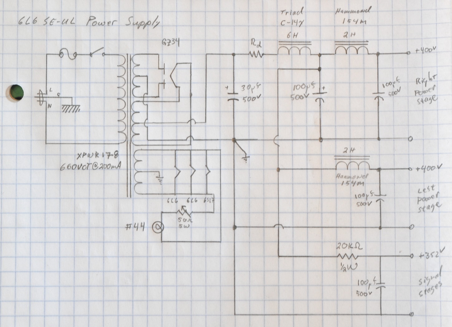
Here is the power supply schematic I posted back on the 16th of June which shows the connection.
I’m actually surprised that one has mentioned it yet. At least in connection with this amplifier.
I should point out that you don’t have to use this approach. It is perfectly acceptable to take the B+ from pin 8 on the rectifier socket and simply insulate and stow the 5v filament winding center tap. This is just a slightly different (and more elegant IMHO) approach to power transformer wiring.
As always, questions and comments are welcome.
Thanks for the note about the rectifier. For your last amp (6AS7) you took the power from pin 8. Based on your explanation, it was likely because the 5v line in that PT did not have a center tap.
Correct. The Edcor XPWR163, the power transformer used for the Purpleheart SET, has a 5v winding without a center tap.
Very nice. Amazing work. Still listening to the 6336 SET.
A center tapped filament winding was very common in industrial tube type rectifier systems.
Almost a necessity for directly heated thyratron tubes used as controlled rectifiers in motor controllers. (Thyratrons had a nice gasseous glow when they were operating unlike SCR’s which just sit there.)