
So what does one do when needing to keep twelve signal paths clearly separated and easily identified in a chassis? Actually the answer is remarkably simple.
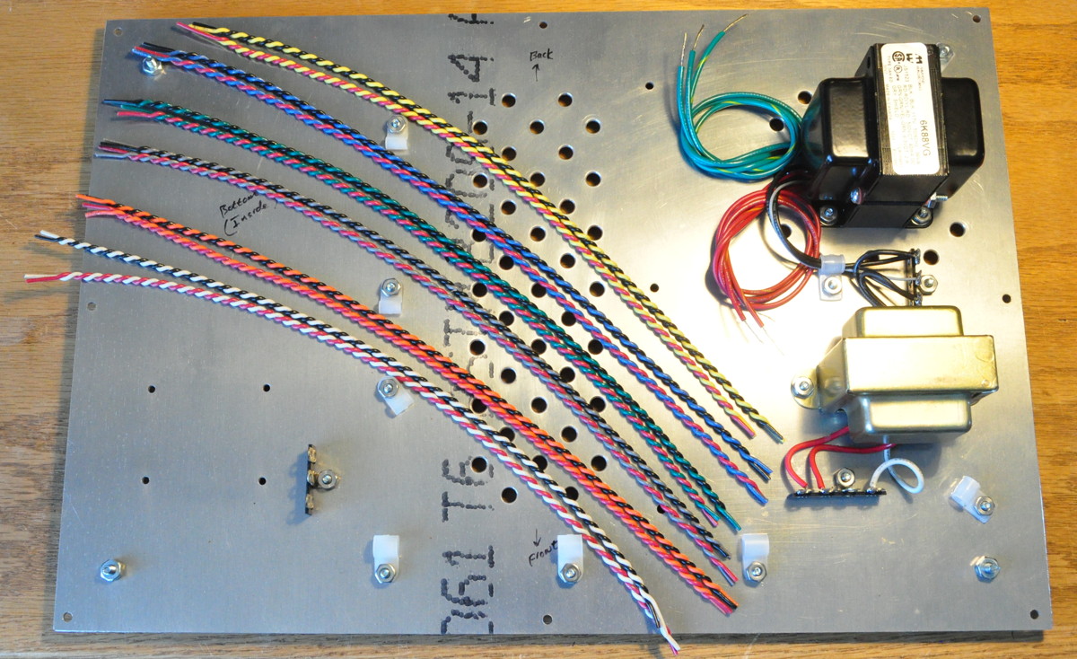
All that you have to do is pull down the multicolored wiring kit from the shelf and make up some twisted pairs.
In this case I needed to be able to easily identify both right and left channels for six separate inputs. So the first thing I did was make a decoder table and assign colors. Here’s that table.
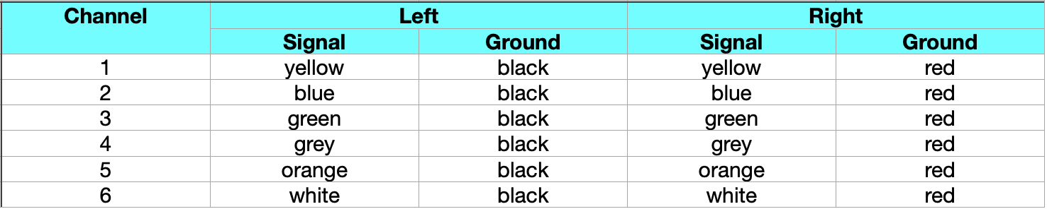
For each of the six channels, the signal line is a distinct color. And for each color, the left and right channels are identified by the color of the signal ground tie. This gives twelve combinations which may be used to uniquely identify each signal path. After that, it’s a simple matter to make up a set of twisted pairs to use for wiring the project.
This is a good idea for several reasons. First, when soldering up the selector switch this will help me make sure that proper contact is being connected to each channel. Being able to verify this before I even install the switch will help minimize problems later. Second, this allows me to bundle the wires in the chassis before soldering up the input jacks. All I have to do is look at the table to determine which twisted pair goes to each jack. This helps keep things neat and to avoid mis-wiring inputs. Third, and probably most important, any time I want to open up the project to do any investigations or troubleshooting I can immediately identify signal paths without tracing wires and applying labels of some type. This is a huge time and frustration saver down the line.
Some people may argue that I’m really going to too much trouble just to identify some signal paths. But I don’t believe so. I once tried to help someone who had built an amp which had a horrible hum problem. When I opened it up, I discovered that he had wired the entire project with a single color of wire and paid no attention to routing whatsoever. This may be an extreme case but that problem was very difficult to solve precisely because of poor design and build decisions at the beginning. Some basic color coding rules, attention to routing and lead dress, and maybe some use of twisted pairs may well have prevent the problem in the first place. And I know it would have made the troubleshoot phase much simpler.
As always, questions and comments are welcome.
Ingenious idea. Engineers love to organize our work flow, just not our desks.
Do you suggest using these twisted pairs for RCA inputs & outputs?
Thanks for all your postings. Go Seahawks.
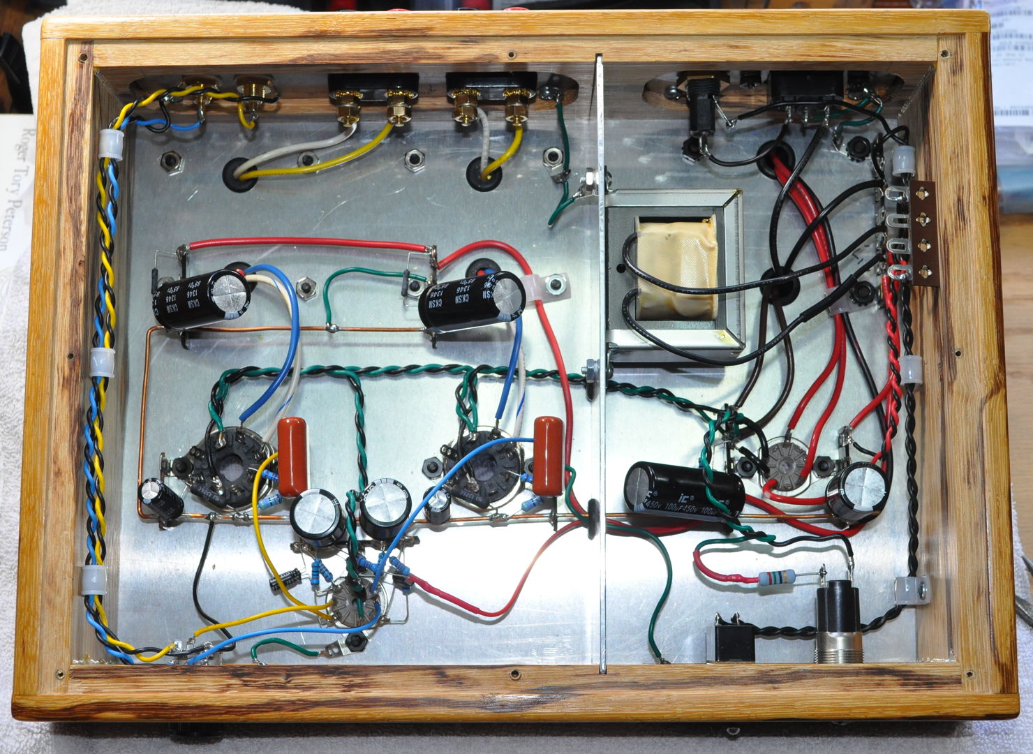
I almost always use twisted pair for signal inputs on amps as well. Here’s the inside of the Marblewood amp with the inputs running down the left hand side from the RCAs on the back to the volume control up front.
Completely justified. Did you use solid or stranded, and what gauge?
These twisted pairs are all stranded 20AWG series UL1007 hookup wire. I have found that making twisted pair with anything smaller than 20AWG stranded wire doesn’t work so well. The resultant pairs tend to partially unwind. I could have used a smaller solid core wire however I didn’t go with solid core because I wanted more flexibility for routing.
‘Nuther question:
Do you find twisted pair signal lines as effective as shielded cable?
My own personal experience indicates that simple homemade twisted pair cables are as good as shielded cables.
Twisted pairs and shield lead actually provide very different types of noise immunity.
Twisted pair is used to minimize magnetic coupling. It is most effective for preventing interactions with stray magnetic fields and preventing the spread of self generated magnetic fields. This is why I always use it for heaters so that the higher heater currents don’t generate stray 60Hz magnetic fields in the chassis.
Shield lead is designed to protect against large AC electric fields. It’s good for instrument cables because they are long (and hence can cross large stray potentials) and carry very small voltages so low level coupling is an issue. The only place I use shield lead in a chassis is where I’m carrying very small voltage signals or the chassis contains a high gain (think greater than 30dB) signal chain.
In the vast majority of projects I build, there aren’t any large enough alternating electric fields to require the use of shield lead.
Are you going to use green/green for the 6V filament lines?
Typically I use green/black twisted pairs for 6.3v filament wiring. Not that I have any Earth shaking reason, it’s just what I normally use.
Although, I seem to have used green/red on the 12AU7 “Color” Preamp. Perhaps I was still in a Christmas mood at the time.
The one thing I’m consistent at is my inconsistency. 🙂
I saw you used green/black & green/red already. So, I thought green/green like the transformer leads was the next option. Your system looks awesome!