
I carved out some more time to work on the amp today. I managed to get the entire power supply section wired in.
Of course, this doesn’t include the main inductor or the main dropping resistor (if required). These get wired in after the top plate is mounted to the chassis. Here’s how the underside of the top plate looks this afternoon.
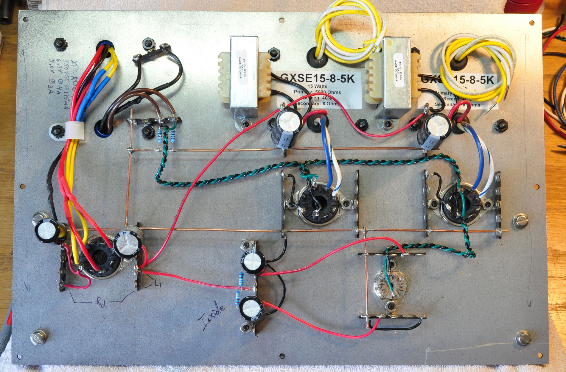
The reservoir capacitor is to the left of the rectifier socket. This was in place in the last update. But now the main filter cap is in place to the right of the rectifier socket as well as the four separate isolation filters. These are two L-C filters for the power stages and two RC filters for the signal stages.
I know that some people consider this power supply approach excessive. But this approach yields both a hum free amplifier and virtually guarantees excellent channel separation. It’s only four additional electrolytic capacitors and two inexpensive chokes. Personally I think it’s well worth the minor cost and effort. And now that this is done, it’s time to get started on the amplifier proper.
As always, questions and comments are welcome.
Nice work as always , Matt. I agree with you on the power supply design-well worth it for the peace of mind knowing that the amp will be quiet and hum -free.
Also, unless I missed it, have you posted the schematic for this amplifier?
Nope. I haven’t posted the schematic yet.
The amplifier itself is very similar to the Marblewood. The only differences being that the power stage cathode resistor is 400Ω instead of 392Ω and the output transformer is a GXSE15 instead of a GXSE10. The bigger differences are in the power supply. I’ve gone to a 5U4 rectifier for starters. The reservoir capacitor has been reduced to 33µf to increase conduction angle. Finally, the 200Ω resistors in the Marblewood power stage final RC filter have been replaced with 1H chokes to form an LC filter stage. Additionally, this change has a particular benefit which I will explain after the amplifier testing is complete.
Wouldn’t a smaller reservoir capacitor increase the ripple that downstream filtering needs to deal with? How would the increased conduction angle affect the RMS current through the transformer secondary? What is gained by the increased conduction angle?
Just some questions.
You are correct in your assessment that a smaller reservoir capacitor results in increased ripple magnitude going into the first filter section. However, so long as the overall filter design is sufficient to meet my -90dB ripple requirement (which it is; with margin) this doesn’t matter. It’s more about the benefits to the transformer.
The transformer secondary can only supply current when the half primary voltage exceeds the steady state DC voltage on the reservoir plus the rectifier drop. This means that the current only flows in a portion of the 180° cycle. This is conduction angle. The consequence is that the power supplied by the transformer to support the DC current at the filter output must all be supplied only when the rectifier is conducting. The consequence being that the pulsed current through the secondary is between about four to eight times the total dc current draw on the supply. This high pulsed draw is hard on the transformer.
The transformer secondary has a set resistance. But the power lost to this resistance is proportional to the current squared. So the secondary heating seen with the rectified supply is much higher than it would be if the transformer just had a resistive load. By lengthening the conduction angle, this peak current is reduced because the power can be supplied across a longer conduction angle. This reduces not only transformer heating but mechanical forces in the windings which can lead to humming transformers over time. The longer conduction angle and lower steady state peak repetitive current also reduces hysteresis loss in the transformer core which also lowers temperature and makes the transformer last longer and perform better.
So, just like all the other decisions, it’s a balancing act. Since I’m using multiple stages of filtering with extra margin, I like to reduce the first capacitor size to improve power transformer performance and lifetime.