
Or… maybe not.
I was all prepared to type up a nice fiery rant about circuits, terminology, and internet ignorance. However, it’s a nice cool and rainy day here at CascadeTubes and I just can’t find the energy for that. So maybe I’ll go for something a little cooler to match the current weather.
This all started the other day while reading a forum post where the author said he wanted to build a project and was asking for a “schematic”. Now I really can’t be sure what the poster meant by the word “schematic” but I had my suspicions. And it was my feeling was that he, in fact, did not want a schematic but rather a wiring diagram.
Some people may accuse me of splitting hairs but I’m really not. And this goes back to the phrase “screams at internet” from the title. I fully realize that most people, especially non-Engineers, use the word “schematic” to mean a wiring diagram for a specific circuit showing how the various parts are connected electrically. But strictly speaking that’s not what a schematic is. I say this because I can take a single circuit, which is a collection of components and substrates electrically connected in a specific manner, and draw any number of different schematics for that same circuit.
The fact that this is possible means that a schematic is NOT just a diagram showing electrical connections. A schematic is really a topographical model of a circuit used to perform analysis. And that topographic model can and does change based on the type of analysis desired and the parameters under which the circuit is to be analyzed.
Here’s an example. The following image contains two different schematics. I assure you that they are both correct and both for the exact same physical circuit. They just make different assumptions. I have intentionally not labeled circuit values to help make the point.
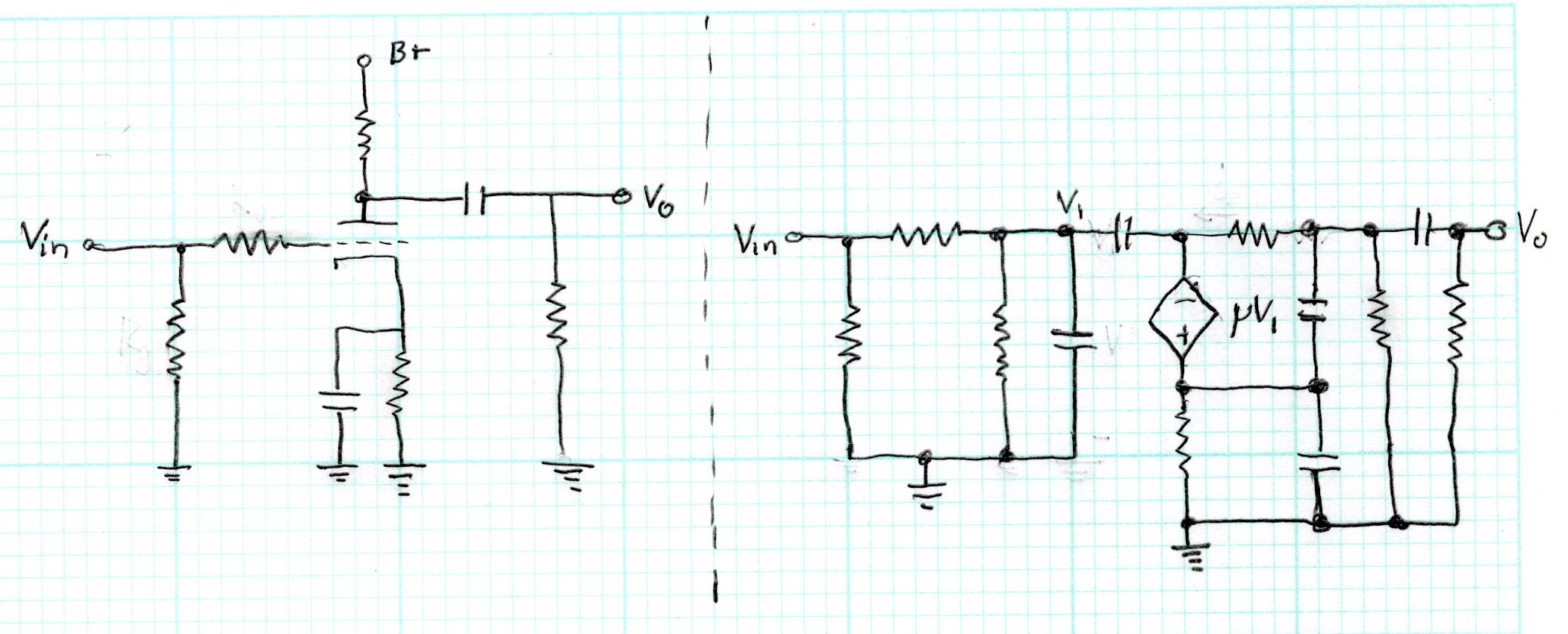
These are two different schematics for a single common cathode triode voltage amplifier stage. The schematic on the left is the one probably much more familiar to most people. But that schematic on the left has some serious limitations. Remember above when I said that a schematic is really just a model? Well both of these schematics are models but each is used for very different purposes.
When I think of a schematic I think of model and how it helps me build mathematical equations which describe electrical behavior. The schematic on the left is a bulk model. This helps us write equations for the DC operating point but it is far too incomplete to describe how the amplifier functions. The schematic on the right is the small signal AC model. It is also incomplete lacking anything to helps us deduce operating points or values. However, we can use it to write all the equations which will completely describe the small signal AC behavior of the amplifier. Together they provide enough information to describe the normal operation of the circuit.
When you lay out a circuit using spice the software actually develops different sets of equations (actually numerical matrices to be use in a linear algebraic solver) based on the analysis required. A DC analysis returns operation point and steady state conditions. An AC analysis generates small signal behavior based on an assumed input. And neither of the models will tell you how the circuit behaves when the basic assumptions are violated. Things like overload conditions and large signal distortion behavior are beyond both of these models.
There is a point I am trying to make in all this. When we think of a “schematic” the first thought that comes to mind should not be physical connections but rather the mathematical model which will help us understand how the circuit functions and behaves. And I’m not saying that it’s necessary to reinvent the wheel and do complete mathematical analysis every time we want to use a triode voltage amplifier. But rather when questions arise, we need to develop enough understanding to help us expand that basic model to include those items which will help us answer those questions.
I know that I talk about the Herbert Reich text a lot (“Theory And Application Of Electron Tubes”, Herbert J. Reich, Ph.D., 2nd edition, 1944) but there’s a very good reason. His text lays out the basic principles to help everyone understand how vacuum tubes really function. Chapter 4 of this text is titled “Methods of Analysis of Vacuum Tubes and Vacuum Tube Circuits”. Even if you just skip over the mathematics and study the text, anyone can learn vast amounts about how and why these devices function the way they do. And these same principles apply regardless of the technology. If you instead read “Modeling the Bipolar Transistor”, Ian E. Getreu, Tektronix, 1976 these exact same principles are used to analyze how transistor amplifiers work. Throughout both texts you’ll see numerous examples of how and why to use different types of schematic models to help understand circuit operation.
So that was the genesis of my non-rant. Words have meanings and I think we all communicate much better when we take time to understand what the words mean and to carefully chose what we say. If the original poster on that forum had said he was looking for a circuit rather than a schematic his intent would have been much clearer. And I would have had nothing to talk about today.
As always, questions and comments are welcome.
Thanks for the learning today! I agree that it is very helpful when we use words that are adequate to the meaning that we are intending. And though I have been immersed in tube amplification circuit design and building for a few years now, but being untrained in any formal sense, I did not know the distinction that you elucidated. Thanks again!