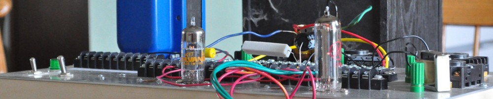
After several false starts, and a couple of minor reshufflings, The power supply side of the new amp is complete. Now it’s time to finish up the actual amp stages and get the top plate on the chassis.
The placement of the capacitor on the primary filter needed to change because (you can all say it with me) I made the chassis just a little too small. Here is the underside of the top plate as it is right now.

By consequence of the placement of the power stage filter inductors, the primary sides of the output transformers are also wired in.
There was a time when I did layout drawings that I would include a “keep out” zone all around the top plate that was about 1″ wide. This always ensured that items protruding through the front and back of the chassis would not interfere with internals hanging off the top plate. Unfortunately I did not do this here. As a consequence, the original placement of the capacitor on the primary filter, that’s the tall capacitor in the lower left, occupied the same space as the socket for the indicator lamp. At first I just thought to bend the capacitor over. However I decided that was a less than optimal solution. So I moved it to it’s current position. This will also make wiring in the primary filter inductor easier when installing the top plate.
Once I get rolling I don’t think it will take me too long to get the remainder of the wiring complete. Then it will be time to see how it sounds.
As always, questions and comments are welcome.
Question; Are there protective grommets on the holes where the power transformer pass to the underside of the top plate?
I see them on the output transformer wires, but not on the power transformer.
No. The output transformer end bells stand proud of the mounting surface. This leaves room for the rubber grommets. The end bells on the power transformer come all the way down to the mounting plane. This doesn’t leave clearance for the grommets.
The holes for the power transformer wiring have heavy chamfers on both the top and bottom of the mounting plate. They are very smooth with no sharp edges to wear through the wiring insulation even if there was an movement in the wires.
OK, thanks.
Another question; Why not something like a 6AX5 as a rectifier to create a more uniform octal appearance?
To be honest, because I didn’t think of it.
A more thought out answer (if I had thought about it before hand) might have said that the losses in the 6AX5 are too high for this power supply design. Given a peak repetitive plate current level of 200mA, the 6CA4 drops about 24v but the 6AX5 drops about 70v. With the additional 46v of diode drop I would have needed a larger power transformer to get the B+ I needed for the new operating points. I could have tried one of the 5v series with a standalone filament transformer. The drop in the 5V4 is close, 27v verses 24v, but finding the real estate for the additional transformer would have been an issue as well.
So, now that I’ve thought about it, it all boils down to trade offs.
Does this answer your question?
Yes