
Ignoring the wood chassis for the time being, I made significant progress on the triode test jig today. I just thought I’d post a quick update. Parts are now mounted and some wiring is underway.
The mounting of all the parts on the face plate is complete. This is how it looks from the outside.
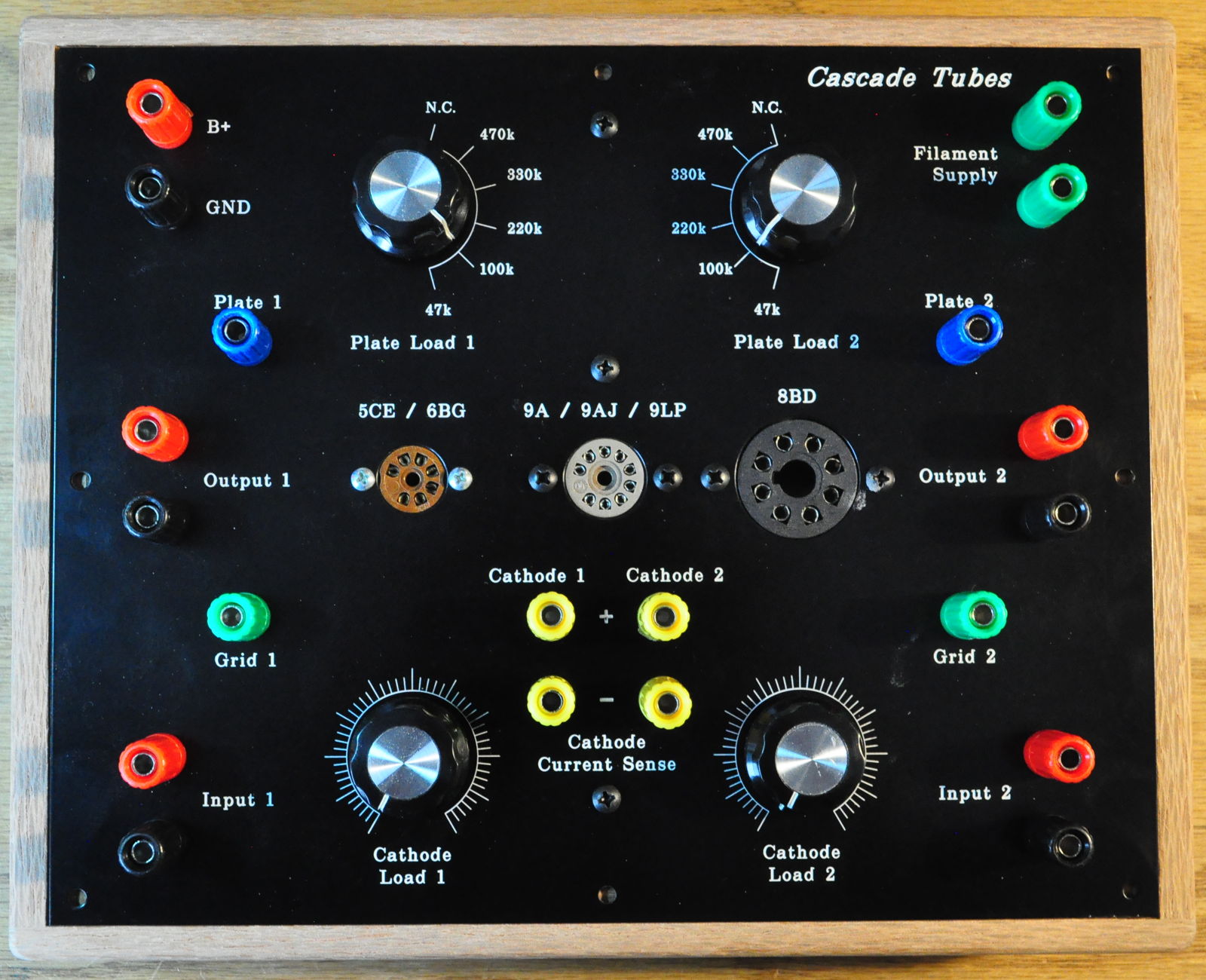
I understand that this may look complicated, but I’ll go over the procedures for setup and operation when I’m done. The minimum set of test equipment to use this jig is a power supply for B+ and filament voltages and a good quality multimeter. That’s it. Now I’ll probably be using an oscilloscope and a dual channel AC voltmeter as well. But it really doesn’t take a ton of extra equipment to make use of this jig.
The other side of the plate is coming along as well. Here’s how the insides currently look.
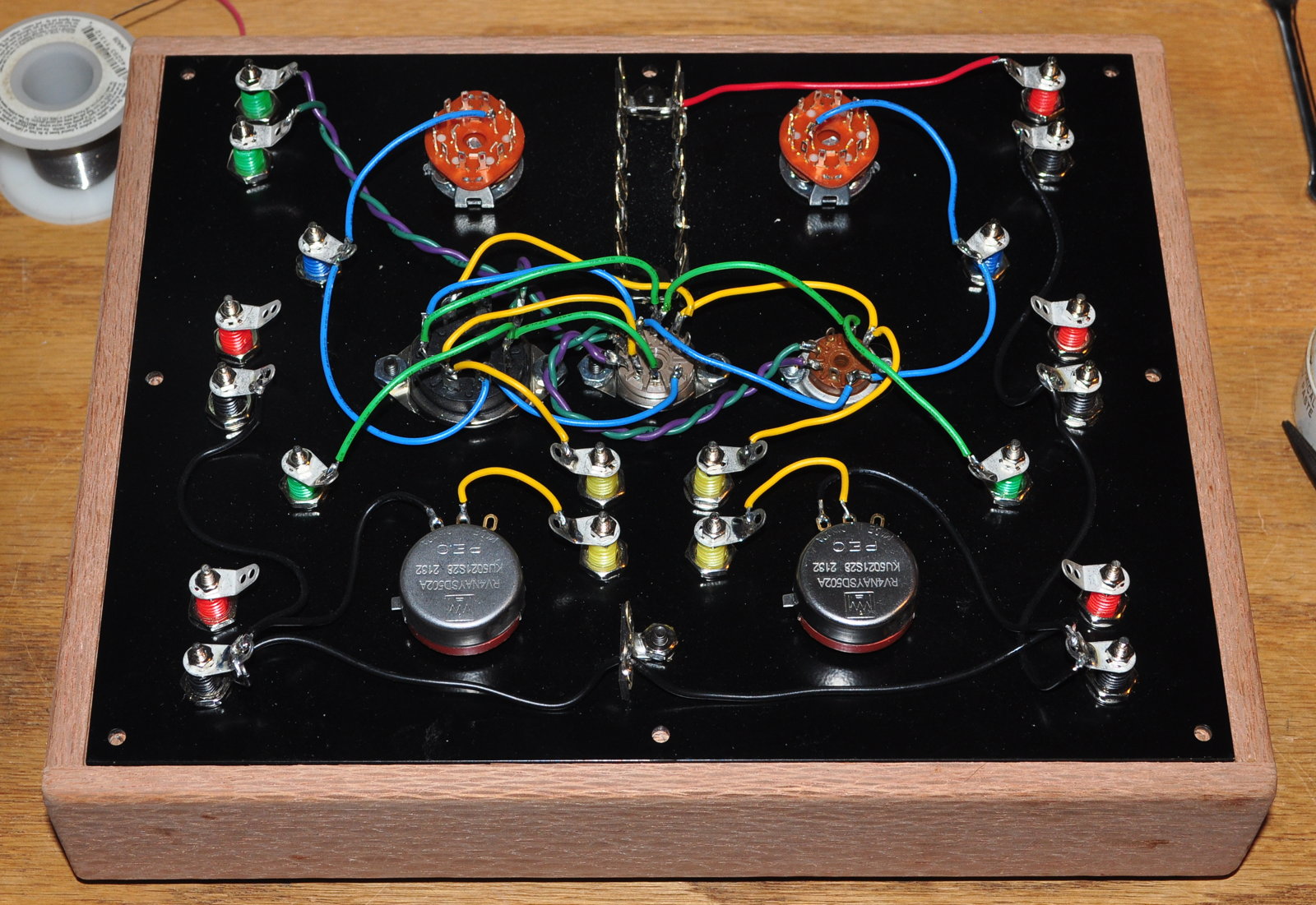
This is with all the discrete wiring complete. Wires are color coded to match the color of the circuit terminals above. Red for B+, blue for plate circuits, green for grid circuits, yellow for cathode circuits, and black for grounds. The only place I didn’t do this is the filament wiring which is a green/purple twist.
At this point all I have to complete on the circuitry is mounting the discrete components (i.e resistors and capacitors). At that point the jig will be fully operational. Then I’ll start writing down the operation and test procedures for testing triodes.
As always, questions and comments are welcome.
Really looks good and professional!