
For a while now, ever since the “Universal Preamp” was posted on the site, I’ve been getting steady requests for a good tube preamp to provide some color to solid state amplifiers. My initial answer to this problem was to design a good quality cathode follower for the Universal Preamp. There was one problem, the volume control.
ATTENTION: There is now a revised schematic for this preamp posted in the post titled “The 12AU7 “Color” Preamp with Improved Buffer”. If you are considering building this circuit, it is strongly recommend that you use the revised schematic.
I originally posted my design on the forum over on the DIYAudioProjects website. However, I was never truly happy with the design. The reason was this; in order to accommodate the cathode follower without adding multiple coupling caps, it was necessary to move the volume control to the input of the gain stage. If you read my post on 4S volume control placement, you’ll understand my problem. This placement seriously restricts the tonal shaping of the gain stage.
This problem surfaces in the back of my mind from time to time. Since I finished the wiring on the test jig yesterday, I was looking for a small project to work on today and this came to mind. Then it hit me, I can do exactly what I did with the Universal preamp and just scale it for the lower impedance. This is one of those ideas I should have had years ago but never did. I was always thinking about high input impedance amplifiers and never clearly thought about the problem of only driving solid state equipment.
It is simply a matter of selecting an output volume control that is large enough to not unduly load the cathode follower yet small enough that the peak impedance will effectively drive a solid state (low input impedance) amplifiers. To accomplish this I designed a good quality cathode follower stage with an output impedance of 575Ω. To this I added a 10kΩ output volume control. The peak output impedance of this pair is about 2.6kΩ. This will drive any solid state amplifier with an input impedance greater than about 10kΩ. This constitutes the vast majority of solid state power amps.
Here’s what the output impedance verses volume setting curve looks like.
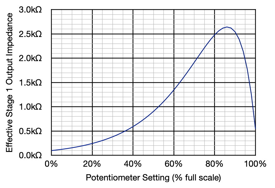
In addition, if significant signal chain gain is not required, the end-to-end gain at the 50% volume setting is about 0dB (i.e. output voltage equals input voltage) and the output impedance is less than 1kΩ. This isn’t as good as the cathode follower itself but it should work very well. And because the volume control is on the output, the stage provides all the tonal shaping desired.
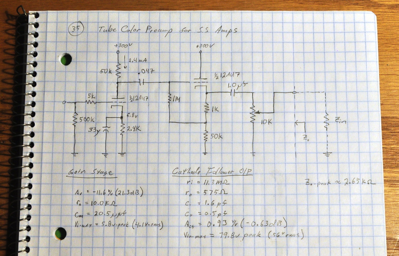
For the gain stage it would have been simple to just use the Universal Preamp design. However, I wanted the ability to provide good gain control (i.e use a lower gain triode like the 12AU7) but provide more color and tonal shaping than the 12AU7 does in the Universal Preamp circuit design. So I went back to the 12AU7 and played with some different loads and bias points. I finally settled on a design which halves the plate load resistance and doubles the cathode bias resistance.
This provides a stage with the additional tonal shaping I wanted to achieve yet increases the bias point so the preamp should never suffer overdrive when driven by normal line level audio equipment. So here’s the final schematic which was recorded in my design notebook.
So now I have a design to truly answer this need. The solid state class-D amps I’ve been using have input impedances between 22kΩ and 30kΩ. This design should drive that admirably. Note that this is not like the Universal Preamp where tubes of various gain may be used. This circuit is specifically designed for the 12AU7 triode. Both for the gain stage and the cathode follower.
I have some new Hammond GK88VG preamp power transformers which just arrived. If I can find a suitable chassis, this should make a quick and rewarding project.
As always, questions and comments are welcome.
Quick question:
Do I see bootstrapping between the output of the cathode follower and its grid?
In solid state emitter to base bootstrapping is frequently used to increase input impedance.
If you are bootstrapping, what is the reasoning behind it in a tube circuit?
Thanks
Never mind, did some reading – the 1K resistor is the actual cathode bias resistor and the 1K + 50K is the load resistor for the cathode follower stage.
The 1MΩ resistor is actually just the grid resistor for the stage. The grid is biased by the 1kΩ resistor. At the design DC operating point (110v,3.71mA) the 1KΩ resistor holds the grid at -3.1v as referenced to the cathode. Then the load (50kΩ) is placed on the cathode side of the plate circuit to bring it into the grid circuit for 100% negative feedback. If one moves the load out of the grid circuit by placing it in the plate lead, this becomes a simple common cathode gain stage.
I should do a post about designing cathode follower stages. It would be long, but interesting.
( I just finished this response when I saw your note. 🙂 )
Pingback: Quick Project for the Preformed Chassis | Cascade Tubes
Matt,
I didn’t even realize you could do common mode rejection with transformers. I was looking into using IC’s with a power supply of positive and negative DC. I will look into you suggestion. It seems better with less components which is less points of failure. Thanks Matt.
Matt,
This is really a good idea for adding some tube color to solid state amps. I have a few Ashley solid state power amps laying around that would need a preamp or some kind of volume control. The input impedance is about 20k if I remember correctly. My only question is, how would I implement a balanced output to this design? Would that change anything? These power amps have balanced input only.
There are two ways to deal with an unbalanced-to-balanced drive. The first is with a crossover cable like this.

However, this method has some drawbacks. Not the least of which is grounding the preamp signal ground to one side of the balanced input. This can lead to ground loop problems. You may be able to minimize problems with a ground lift switch in the preamp. It all depends on the type of circuitry behind the amp’s balanced inputs. The other, much better method, is to use transformer isolation with something like the Edcor WSM10K/10K matching transformer. You can even put these in a small metal enclosure with RCAs on the input and balanced male plugs on the output.