
I took some time this afternoon to get the metal work completed (mostly) for the Source Selector Unit/Preamp. All the drilling is complete and everything is properly fit to the chassis. The only metal work left to do is four holes in the mounting brackets which need to be drilled and tapped. These four screws will hold the top plate in place and make swapping tubes easier.
Tomorrow I’ll get the brackets fit and completed and then it will be time to begin working on finishes. Here’s what the metal looks like today.
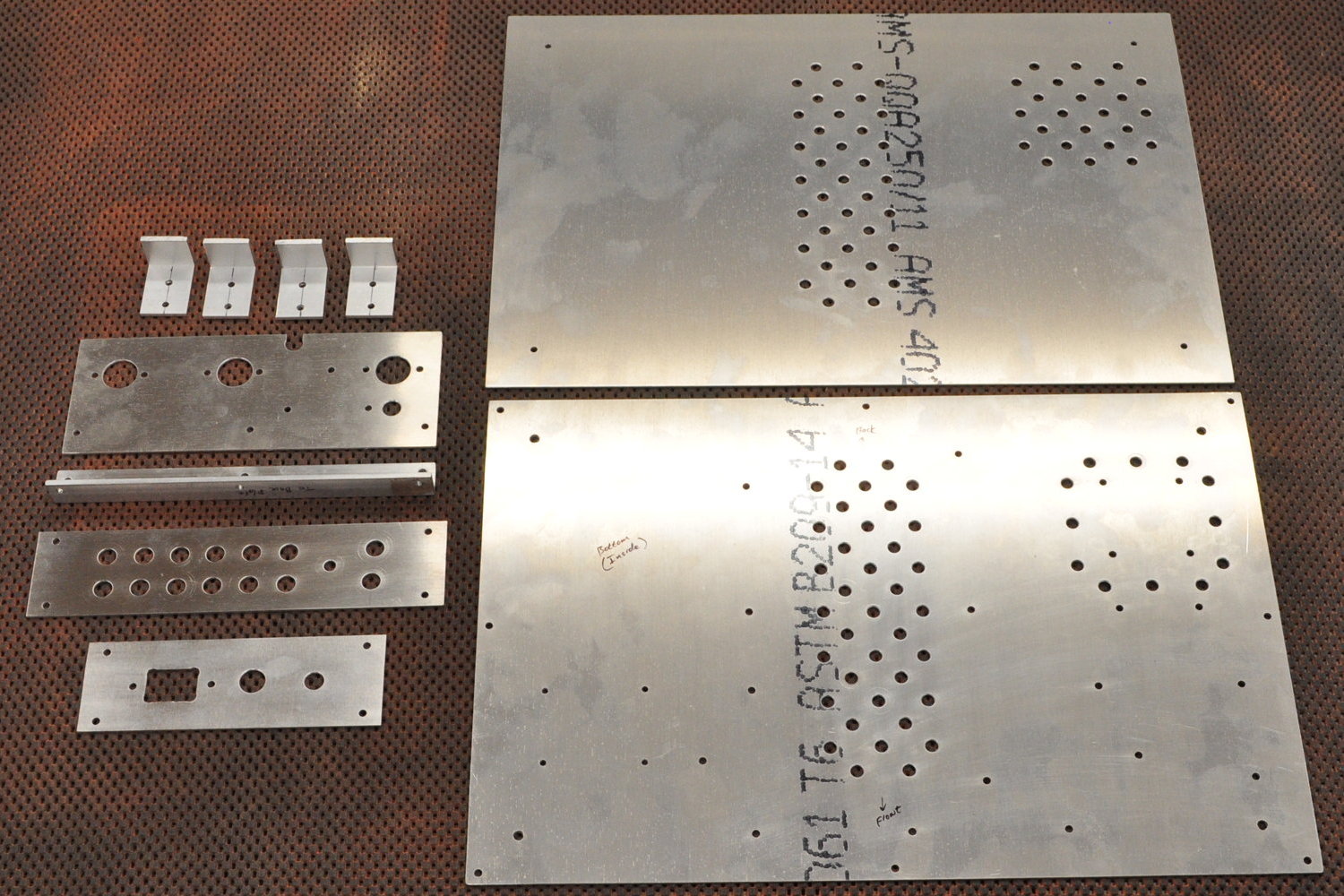
This doesn’t include the front plate from Front Panel Express but it is all the other metal for the unit.
In this picture, the top and bottom are both top side up. This works to show the ventilation paths around the Hammond transformer (because Hammond transformers run a little hotter than others) and the passive air circulation paths up and around the tubes. There isn’t a lot of heat generated by the tubes, around 12W. And I’d estimate about 5W for the Hammond transformer. With everything else maybe dropping a few watts maximum into the enclosure. Call it around 20W maximum heat load for everything. All the same, this amount of heat pumped into a sealed chassis could raise the internal temperature significantly. The venting should keep the internal temperature well below the normal design limit of 80°C with plenty of margin.
The other thing I wanted to touch on is the design of the tube mounting plate. That’s this piece of metal shown below.
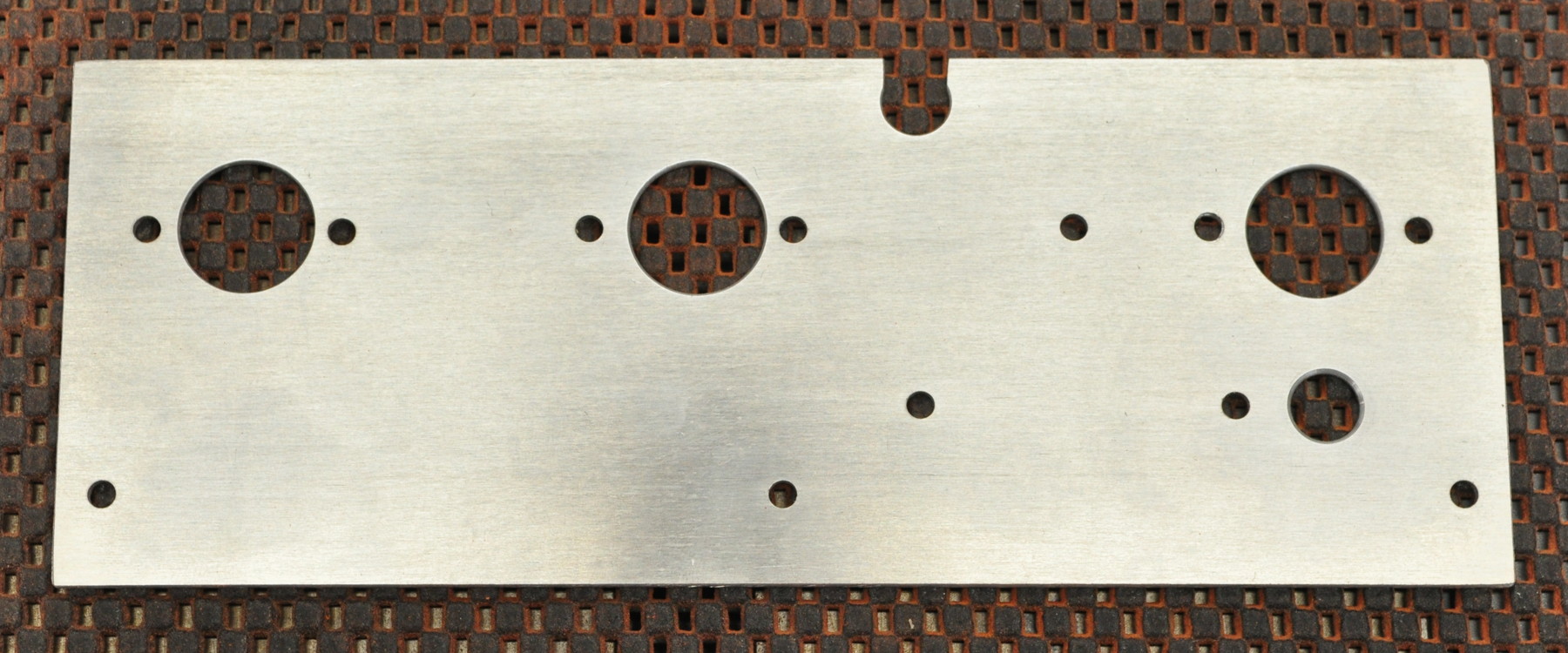
The three larger holes are for the tube sockets. The 3/8″ (9.5mm) hole on the lower right is for passage of the two wires from the main filter choke which will be mounted on the other side with the tubes. The hole with the cutout at the top of the plate is for the left and right signal outputs and the shared ground lead.
Often I see builds where people have run wires through holes in metal partitions or shields. What I think most don’t realize is that the hole in the plate is in fact a ground loop which can lead to ground plane coupling to the amp internals. Here is an illustration of that loop.
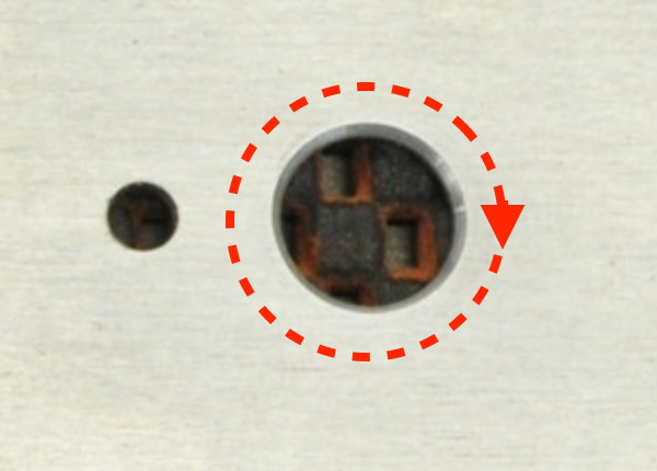
So it helps to understand under what conditions unintended coupling will occur. The level of coupling is directly dependent on the net level of current flowing through the loop. This is how those clamp on AC current meters work. The clamp is a breakable loop which when placed around a wire has a signal induced in it dependent on the level of the current in the wire. So, since I’m wiring the main choke through this hole, shouldn’t there be a bunch of unwanted ground coupling? The answer is “NO”. Note that above I said “net level of current”, not total current. Since both leads from the choke will be running through the hole, and the current in those leads will be equal and in opposite directions, the “net” current will in fact be zero. So in this case I’m not at all concerned about coupling.
But what of the notch at the hole on the top? Well, that notch is for the signal wires going to the output jacks. There will be three; signal left, signal right, and signal return. Here, because of potential capacitive loading of cables and maybe even amplifiers, I cannot be assured that the net current in those three wires will be zero. At least not instantaneously. As such, I took the extra step to break the loop in the ground plane so I don’t have to worry about it under any conditions.
I will admit that the risk to the signals is very low. But I consider the policing of potential ground loops in my designs to be a “best practice”. It’s just another one of those little efforts that keeps any problems to a minimum. And in the rare circumstance that such a loop did cause a problem, it would likely be a very difficult problem to troubleshoot. This is one of those instances where I could end up with modulated RF on the signal lines from a nearby radio station. And nothing is more frustrating than hearing the local 50,000W AM radio station coming through your sound system when you’re trying to listen to a CD.
I just thought I’d take a minute to talk a little about ground plane coupling issues and point out this example of how I attempt to minimize such problems in my design process.
I’ll be finishing up fitting the top plate tomorrow, after I finish some errands in the morning. Then I can clean up the shop and start thinking about applying finish.
As always, questions and comments are welcome.